Today we’ll be making a modification to the Standalone Temperature Logger which will allow us to log voltage instead of temperature. I would like to log the voltage of a 12 volt battery or the small solar panel that’s charging it, so I’m aiming for a voltage range of 0 to 15 volts.
The ATtiny85 in the SATL is powered by a 3 volt battery and the ADC (analog to digital converter) measures 0 – Vcc by default (3V in this case). How can we use the ADC (analog to digital converter) to increase its range to 15V? We can use a voltage divider to divide the voltage by a certain ratio.
Choosing a voltage reference
Before starting we need to find a voltage reference which is independent of our voltage source because we are measuring something that isn’t on the same power supply. If we used our voltage source as the reference then the battery voltage could drop by a little and our readings would be off as you’ll see in the example below.
For example, assume we have a 1/8 voltage divider and we are measuring 12 volts and our Vcc is 3 volts.
3V (voltage reference) / 1024 (10bit ADC) = 0.00293 value per bit
12V / 8 (voltage divider) = 1.5V
3V / 1.5V = division of 2
1024 bits / 2 = 512 ADC value
Our program would read the 1.5V ADC as 512, times that by the value per bit 0.00293 (this value stays constant and would be stored in our code) and then times that by 8 which would give us 12.00128 volts.
Now if our Vcc changed to 2.92 volts it would give us:
2.92V / 1024 = 0.00285 value per bit
2.92V / 1.5V = division of 1.946
1024 bits / 1.946 = 526 ADC value
Our program now would read the 1.5V ADC as 526, times that by the value per bit 0.00292 which we had previously, times by 8 to gives us 12.28736 volts.
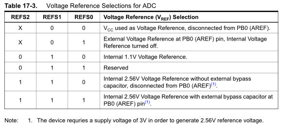
Luckily for us the ATtiny85 has two voltage references that we can use which are 1.1V or 2.56V. However you’ll note that if we use 2.56V our Vcc needs to be 3 volts or above which isn’t something we can guarantee with a 3V coin cell, so we’ll use the 1.1V reference.
Also it’s good to note that the 1.1V or 2.56V internal references do have minimum, typical and maximum values which varies with temperature.
Over-voltage protection
We’ve chosen 1.1V as our voltage reference however what would happen if somehow the voltage rose past that? It’s a rare case in the application I’m using but if it was the case, something bad would happen. The first thing I thought would cover this would be the zener diode however it appears that there aren’t any 1.1V zener diodes available. The next component that comes to mind is a standard diode with a nominal voltage drop of 0.7V but we’ll use 0.6V as the voltage drop (I get about 0.613V with a meter).
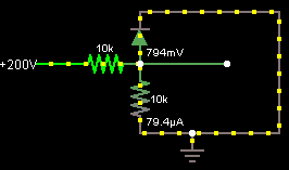
Just as an example if somehow there is 200 volts, it will all be directed through the diode and bypass our ADC. The downside to this is that we’ll lose the ADC range between 0.6V and 1.1V which is almost half of our ADC scale of 0V to 1.1V.
Calculating the voltage divider ratio and simulation
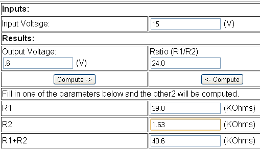
Now we can actually get on to the fundamentals of calculating the voltage ratios and to make our life easier there’s a website which can do this for us: http://www.daycounter.com/Calculators/Voltage-Divider-Calculator.phtml
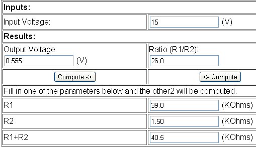
So we’ll enter in the input voltage of 15V (our maximum) and output voltage as 0.6V, the result for our voltage ratio is 24. We can now enter in the value of our Resistor 1 (R1) and it will calculate R2 for us, I’ll use a 39k resistor for R1 and it gives us 1.63k for R2.
I’ll re-calculate the ratio/output voltage to suit a 1.5k resistor for R2 as I don’t think there are really 1.63k resistors around. We add one to the ratio result to give us 27 which we’ll use in our calculations.
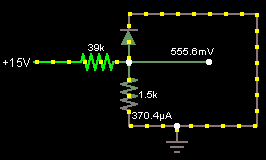
Let’s simulate this with Circuit Simulator and re-do our calculations which we did in the start.
1.1V (voltage reference) / 1024 (10bit ADC) = 0.001074 value per bit
15V / 27 (15V/0.555V) = 0.555V
1.1V / 0.555V = division of 1.98
1024 bits / 1.98 = 517 ADC value
Our program would read the 0.555V ADC as 517 which we times that by the value per bit 0.001074 and then times that by 27 (which will always be constant ) would give us 14.9919 volts.
11.99V / 27 = 0.4440V - Start
12.00V / 27 = 0.4444V - Change not detected
12.01V / 27 = 0.4448V - Change not detected
12.02V / 27 = 0.4451V - Change Detected
12.03V / 27 = 0.4455V
As above, we can see how much variance in the voltage we can detect which is 0.03V which is pretty good considering we are only using about half of the range of the ADC.
A Quick Test
I did a quick test with a 12V battery at 12.17V and a multimeter measuring the voltage divider. It appears that with a diode the voltage read 0.408mV and without the diode it was 0.450mV. The correct voltage should be about: 12.17 / 27 = 0.450mV, so we can see that a single diode is not enough, we’ll need 2 diodes.
Improvements which we could make would be to increase the resistance of the 39K and 1.5K so that it won’t always be draining 0.3mA at 12V.
Updated Schematic
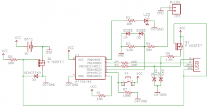
We can now update the schematic to show the voltage divider.
Code changes
int VoltagePin = 3; // Analog input 3
...
float vRefperbit = 0.001074;
int vRatio = 27;
We firstly need to add two variables, the voltage reference per bit and the ratio between the battery voltage and voltage divider’s voltage.
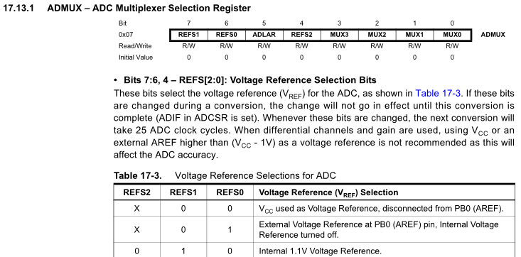
Next we need to change the analogRead function to select a voltage reference of 1.1V instead of Vcc.
int analogRead(uint8_t pin) {
  ...
  ADMUX = (1 << 7) | (pin & 0x3f);
  ...
}
This is done by changing ADMUX to add in setting REFS1 (bit 7) to 1.
// Log Voltage
if (functionSelect == STARTLOGGING) {
  int voltValue = (analogRead(VoltagePin));

  // Split 10bit voltValue (0 - 1024) to high and low byte and write to EEPROM
  if (dataCount < 510) {
    eeprom_write_byte((uint8_t*) dataCount, (voltValue >> 8));
    dataCount++;
    eeprom_write_byte((uint8_t*) dataCount, (voltValue & 0xFF));
    dataCount++;
    if (dataCount < 510) {
      eeprom_write_byte((uint8_t*) dataCount, 254); // So we know where to stop when extracting data
      eeprom_write_byte((uint8_t*) (dataCount+1), 254);
    }
  }
  else {
    functionSelect = WAITINPUT;
  }
  ...
}
Now we need to change how we store the ADC number in the EEPROM because our value will range between 0 to 1024 (but since we are going to 15V it’s really only 0 to 517). Since each location of the EEPROM can only store 1 byte (255) we can use 2 locations and split the ADC number up into 2 bytes. The high byte will be stored first and then the low byte which means the maximum number of reading we can store is 255 (255 x 2 bytes = 510 + 1 byte for delay time setting). Before we used to place the number 0 in the next EEPROM addresses to indicate the end of the logging however since 0 is now a valid number, we change it to 254.
// Send the next digit from the EEPROM address
int sendnextDigit(int eepromAddress) {
  uchar digit;

  // Re-construct 10bit voltValue (0 - 1024) from high and low byte from EEPROM
  byte highByte = eeprom_read_byte((uint8_t*) eepromAddress);
  byte lowByte = eeprom_read_byte((uint8_t*) (eepromAddress+1));

  unsigned int combinedValue = (highByte << 8) | lowByte; // Combine high and low byte

  if (combinedValue == 65278) { // 254 high and 254 low byte
    return 1;
  }
  if (combinedValue == 65535) { // 255 high and 255 low byte (testing USB communication)
    combinedValue = 0;
  }

  double value = (combinedValue * vRefperbit) * vRatio; // Calculate ADC value to voltage level

  char tempValue[7];
  dtostrf(value, 3, 2, tempValue); // 3 character (including dot) minimum, 2 digit precision

  nextDigit = &valueBuffer[sizeof(valueBuffer)];
  *--nextDigit = 0xff;
  *--nextDigit = 0;
  *--nextDigit = KEY_RETURN;

  // Break up the number and convert to USB HID values
  int x = 4;
  if (tempValue[1] == 46) { // 46 = ASCII Dot detected after 1 digit, only send 4 characters instead of 5
    x = 3;
  }
  while (x >= 0) {
    digit = tempValue[x] - 48;
    if (digit == 0){
      *--nextDigit = KEY_0;
    }
    else if (digit <= 9) {
      *--nextDigit = KEY_1 - 1 + digit;
    }
    else {
      *--nextDigit = KEY_DOT;
    }
    x--;
  }

  return 0;
}
The last change is when sending the data to the PC. We re-construct the ADC value from the EEPROM by combining the high byte and low byte together. If this matches the number 65278 (254 high byte, 254 low byte) we have reached the end of the data to transfer or if it matches 65535 (255 high and low byte) we are testing the USB communication. We apply our formula to change the ADC value to a voltage such as 12.18 and then use dtostrf to convert the double into a string so we can easily process it.
char* dtostrf     (     double      __val,
signed char      __width,
unsigned char      __prec,
char *      __s)
With dtostrf, the width is the minimum string we will create including the dot, this would be 3 for example, 0.0 volts. The prec (precision) is how many numbers we will use after the dot, in this case we can just use 2 for example, 2.53 volts.
Next we check where the decimal place is so we can adjust whether we should send 5 characters (eg. 12.43) or 4 characters (eg. 2.53) to the PC and then we read each character in the string and subtract 48 which converts it from an ASCII number to an integer (the number 0 is 48 on the ASCII table, number 1 is 49, etc). We check if the result is actually a number between 0 to 9 and if it’s not we print a dot.
Testing it out
I tested this modification on a AA battery, AAA battery, 9V battery and 12V battery all of which reported an accurate voltage close to 0.03 volts. I did find that if using an old 3V coin cell (down to 2.95V) without a small capacitor it would report 0.17V when there was really 0V, just something to keep in mind.
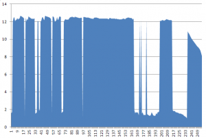
I decided to measure my small solar panel every minute which is shown below.
As you can see it looks like I’ll need a higher voltage solar panel as this one is hitting 12.5V in direct sunlight which isn’t quite enough for charging a 12 volt battery.
Download
v1.1 (8 November 2011) – Download
– Updated to include capacitor, 2 over-voltage protection diodes replaced for a DO-35 type and replaced 39K/1.5K resistors with 390K/15K
– Added PCB Etching
– Fixed bug when configuring delay time. If button was held down before any delay time was set, nothing would happen
v1.0 (5 November 2011) – Download
– Initial Release
Notes: You can log voltages up to 27 volts if you remove the 2 diodes for over voltage protection. If the range needs to be increased even higher and you are happy with less accuracy, modify the resistor ratio to suit your needs.



Aren’t you manufacturing/shipping these units?
I guess, this could be easily used in a form-factor of a cigarette lighter for testing alternator/rectifier in the car. Personally, I’d eagerly pay $10 for the ready-made board shipped to Russia 😉
Hi, thanks for your interest :). I haven’t started manufacturing or shipping the SATL or this mod but I have been thinking about doing a PCB for the SATL for a while.
It depends what you mean by the “ready-made board”, would it be the PCB itself or the PCB and components? If it’s the PCB by itself, then I think that price is achievable.
hm, what are your cost estimates for this board (supposing, you’d make at least 10 of them and intellectual, creative component – design job – was made for fun)
next question – will you use PCB professional service, or replicate pcbs at home using a laser printer and an iron?
okay, what would be the final price for the whole board with all elements soldered and programmed?
I would definitely use a PCB professional service, doing it at home isn’t worth it. I have checked around for the PCB services (like ITlead and Seedstudio) which are pretty cheap. So I think $4 (AU$) for the PCB board itself should be reasonable?
For all components with ATtiny85 pre-programmed but nothing soldered, I think $14 (AU$).
For everything soldered (not something that I would want to do as a regular thing, would prefer users make it themselves) I think $20 (AU$).
The part that costs so much is the ATtiny85! There is another supplier with a cheaper price but none in stock, prices could drop another $1 if they can have them in stock.
Shipping isn’t included in the costs, I think it might be $2.50 for international postage by a letter.
Well, I believe, 4 AUD is a reasonable price for a bare PCB. However, from the economy perspective, as the size of the board is very small, I’d say you can have a few dozens of them for the price of 15 AUD (providing you have a decent laser printer and an iron). May be they wouldn’t look like those professional made, but judging by my first experience this summer, the result is pretty nice.
Okay, charging extra 6 dollars for soldering works sounds reasonable. Btw, dealing with pb-free PCB (correct me if I am wrong – I believe, the most of professional-grade PCBs are made using this plumbum-free technology) is a different story.
But do you really think all those components cost $10?
All in all, for me it’s just the matter of usefulness and its relation to the cost. And from this point of view, as I don’t possess any solar cells, the temperature logger is much more useful 🙂 But once again, $22.5 for a temperature logger is a bit more than I think I can afford. (Actually, I need three of them)
Couple of questions: have you tested your temperature logger against harsh weather environment (low temperatures, to be exact) – can I leave it at my country house for the winter season? (the temperatures here can drop down to -40C or even lower) – will the battery survive and what happens when the ambient temperature descends below the operating range of the device?
I think it’s just the time aspect of making the boards which would be easier to have it professionally made. A large benefit is through-plated holes when professionally made because right now you have to solder some component leads from the top and bottom of the PCB which can sometimes be hard.
For the PCB, PB-free I think Seedstudio has the option for an extra $5 for the 10 boards. I wouldn’t go with the PB-free PCBs (unless there was a demand for it).
The components don’t cost $10 and for sure you could grab the components much cheaper but I’ve just left some room for margin because it wouldn’t make much sense to provide everything to near cost price.
I agree that the price of $22.5 does seem a lot for a temperature logger assembled (BTW the price was for the voltage logger, it should be almost the same for the temperature logger) but it will always be cheaper for users to source the components themselves and solder it all, I guess it’s just a time trade-off – would you rather spend your time making it or have someone else spend their time.
I have only been able to test it to -18C (my freezer) today for about 9-10 hours in a sealed small box and it seemed to be fine. I checked the battery voltage before and after inserting into the freezer and there was only a 0.01V drop but a real test would be to leave it there all week! The life of the battery would be reduced but since we don’t draw much current all the time, I think it shouldn’t affect voltage too much.
-40C is the amount specified by Atmel for the ATtiny85, so if it’s lower than that it could still work fine or there could be some glitches that might occur, it would just be a gamble however I think that there is a good chance it should be fine.
Most of the coin cell batteries are rated for -20C, so at -40C it may experience a high loss in voltage, if it drops to 2.8 then it’s very close to the minimum rating required by the ATtiny85. (For temperatures lower than -40C the code will need to be modified slightly)
I’m wondering if you have you ever left a 3V coin cell in the cold like -20C to -40C and if so what was the voltage like? I would be interested to hear if there was a major voltage drop.
I haven’t done any tests yet – that was just an idea. I wanted to leave these temperature loggers in various points of the country house to log day and night temperatures (twice a day) during a month (may be two or three months). As it is located in the lowland by the riverside, the temperature there is sometimes 10-15C lower than that in the city. I guess, -20–25C is a usual for the city, that’s why I reckon we can see -30–35C at my country house.
This winter hasn’t begun yet, but I’ll ask my dad to carry out such an experiment once the temperature drops down.
btw, I didn’t find any pcb layout in that archive – or is it the same as in the temperature logger?
I didn’t make one, I’ve now updated to v1.1 and included the PCB layout, it’s similar to the temperature logger one (and has more diodes/resistors and a cap) but things are moved around a little. (Note: the PCB hasn’t been made/tested as yet)
The point inside rectangle (overvoltage protection and calculating divider) is supposed to be connected to the µc ADC pin?
Look, if my fuel level gauge is basically an ohmmeter with the power source of 10V (±0.2V), can I hook my µc in parallel to the gauge unit inside the binnacle? Will that affect the readings? Am I right that ohmmeter is a voltmeter + stabilized voltage source?
Any idea on how to source everything in the automotive environment? I’m afraid of voltage peaks and need an advice on overvoltage protection (how do I install zenner diode, if I find a suitable one?)
one more question: why do we use lm7805 while we can use a zenner?
Yes the point that reads 555mV when testing should go to the ADC pin but it’s missing another diode from that. If you check the updated schematic shown, ADC3 is the pin that I use for ADC.
An ohmmeter would have stabilised voltage source but it might not be the voltage you are after, it could be 2.56V or less so you would really have to disassemble it to find out what the voltage source is.
For sourcing components in the automotive environment, sometimes manufacturers list the automotive parts in the datasheet. Otherwise you could try looking up the manufacturers of the component and go directly to that manufacturers website to see if you can search for an automotive part.
The reason why you wouldn’t use a zener instead of a lm7805 is because the zener isn’t current limiting meaning if you connected it directly to a 10V supply, it would blow up because of all the current flowing through it. Zeners are only useful when the configuration is power rail -> resistor -> zener diode connecting to ground, now the supply current won’t be unlimited and the zener diode can work to reduce voltage. As always, you can prove this by simulation of the circuit.
The workshop manual states that it is a 10V stabilized voltage source. And it says, the resistance of the level sending unit is 19 ohms to 275 ohms, full to empty. These resistances complete the ground circuit to the gauge and cause a deflection of a bi-metallic strip attached to the gauge needle proportionate to the ohm values suppled.
So it turns out my new goal is more complicated than I initially thought. What do I do to be able to leave the stock gauges and have those readings on my microcontroller-based device?
As for lm7805 – does that mean I can substitute the one with a zenner and a resistor?
I’m guessing there would be a microcontroller that is setting the resistance so you could hook up some wires to it and reverse engineer when the master micro sends data to it. Another thing to try is see if there is any voltage drop on that resistor when it changes resistance. Probably a last resort is to cut the wire and add in a 1 ohm resistor and use an AVR to measure the voltage drop on it.
For the lm7805, if you want a stable 5V source go with the lm7805. For zener diodes, they only reduce the voltage to say 3.6v only if certain amount current is flowing. If more current flows (say when you AVR is doing something) then the voltage may drop.
You mean a microcontroller in stock? (the car was made in 1987).
I thought that any resistor connected in serial would lead to a voltage drop. What would that mean?
As for the ‘last resort’ – could you please explain the idea in detail – which wire to cut and how would that prevent my microcontroller from affecting the readings of a stock gauge?
As for 7805 – I got the idea why we can’t use zenner instead. Actually I am using 3.3V, but the problem is to filter those high-voltage spikes. I wish I had an oscilloscope to check the onboard voltage when switching on/off the lights and other loads…
So I assume the circuit is something like this 10V -> variable 19 ohms to 275 ohms resistor -> gauge -> ground.
The last resort is cutting a wires in that circuit and connecting a 0.1 ohm resistor to replace the wire you cut like: 10V -> variable 19 ohms to 275 ohms resistor -> 0.1 ohm -> gauge -> ground.
Now when the variable resistor is at 19 ohms, the voltage drop on the 0.1ohm is 52.36mV and when at 275ohms the voltage drop on 0.1ohm is 3.65mV. Now all you need to do is put the ADC wire in the middle: variable 19 ohms to 275 ohms resistor -> ADC wire here -> 0.1 ohm.
you mean like this?
http://goo.gl/Cm4mi
and the µC’s ground should be connected to the gauge’s ground?
Yes like that but assuming that the bi-metallic plate completes the circuit and that it has no resistance. An easy way to check is to probe the variable resistor on both ends and see if the voltage drop on it is 10V.
If it’s less than 10V, then the bi-metallic plate has a resistance which is good, this means the bi-metallic plate could act as the 0.1ohm resistor and you don’t need to cut anything. You would just need a resistor divider to reduce the 9.x volts to something around 1 volt.
If the voltage drop is 10V then you can continue on with the circuit. Before you hook up the ADC, use a multimeter to double check that the voltage of that ADC pin will not be more than 1V.
okay, once I get to the car, I’ll see and report. Meanwhile, I’d try to move from attiny2313 to atmega and add ADC and BOD.
Any ideas on how to source microcontroller in automotive environment and how to protect circuits? (the wires to the hall sensor will be pretty long ~3m)
For the Atmel chips you can find an automotive selection here – http://www.atmel.com/PFResults.aspx#(data:(area:’34831′,category:’34864[33180]’,mature:!f,pm:!((i:8238,v:!(0,17)),(i:8394,v:!(0,17)),(i:8362,v:!(0,27)),(i:8282,v:!())),view:list),sc:1)
For protecting the circuits, you would want to mount the PCB to small box with some air holes and covering all wires going outside of the box with heat-shrink tubing.
uhm. getting ready to see the car. so far I have some time left, so I decided to read the internet, and here what it says:
“The resistance between the poles of the gauge, measured by my multimeter, is .062”
It’s too small, isn’t it?
Besides, what makes the things even more complicated, the stabilized voltage is not constant. It has pulse nature: on-off-on-off (probably, it was designed so to prevent overheating the bimetallic stripe?). So probably I’d have to use another external interrupt, use a voltage divider to run the interrupt when there is voltage in the source, and measure the voltage in the interrupt itself. Is it a good practice?
I don’t see anything wrong with waiting for an interrupt and then doing the ADC inside the interrupt (it can take anywhere from 65 – 260us to do the ADC conversion).
As long as you don’t have an interrupt inside another interrupt you should be fine. Using analogRead from Arduino waits for a ADC register to change state and doesn’t use interrupts.
oh my. this probably explains the pulse nature of the stabilized voltage (if I’m not mistaken):
Inside, it has a coil of resistance wire, effectively an electric heater, wrapped around a bimetallic strip. The bimetallic strip consists of two different kinds of metal bonded together, with different rates of expansion with temperature. So when it gets hot, one side expands more than the other, and forces the strip into a curve. The end of the strip in the VS has a contact that closes when the strip cools, and applies ignition voltage to the heater (and to the gauges). The heater heats the strip up, the contacts open and the cycle repeats.
holly crap! it’s in the age of LM7810 and other similar solutions! probably, that’s the reason my fuel gauge, temperature meter and tacho never report true figures!