So we’ve got our parts and our motor controller so we are now ready to make this robot move forward, backwards and turn. I’m assuming you’ve put the wheels on the motors, mounted them to your design, used a gearbox if necessary and you do have a motor controller. Plus you also have the 9 volt battery and clip for Arduino.
In this part we will need:
- Arduino Duemilanove ATmega328
- 4 x NPN general transistors (e.g. PN100, PN2222)
- 4 x 6.2K Ohm resistors (10K will do fine too)
- Breadboard
- Some wire
Warning: In regards to the NPN transistors, I’ve gone with general use ones which are rated at 500mA maximum. This means that your motors can’t use more than 500mA to run or when it’s stalled (i.e. you turn it on and hold the wheel with your hand not allowing it to spin). If your motor is rated more than 500mA stall, please stop and grab some transistors (e.g TIP 31B/C) that can handle the stall current otherwise you will blow up the transistors.
I’m actually in the process of building my very own very simple motor controller to control both motors bi-directionally. I’m thinking of making a 1 motor and 4 motor as well and all three will be available for sale, so keep an eye on this spot. (At the moment I’m still working out the transistors to use and doing the calculations [I’m new to electronics.. have I mentioned that?!]). If you don’t have a motor controller I recommend buying one for now, they are around $8 to $10 or so to control two motors in both directions.
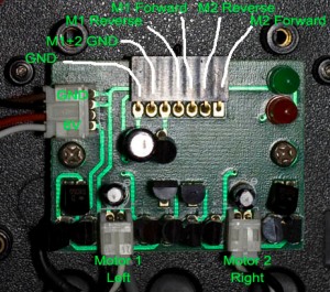
Below is the Cycbot’s motor controller which I’ve labelled to show what pins do what.
As you can see we have two motors with two directions and the both motor’s ground. Also notice the ground next to the motor’s ground, this will be important to us.
So from here you can actually connect the motor’s ground to any of the directions and that motor will spin in the direction, that’s good but how can we switch these connections on and off using another circuit?
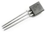
The answer is by using a transistor, in our case an NPN transistor. View more information on transistors here.
Basically the transistor has 3 pins, a base, collector and emitter. In our example, we would connect the Motor 1 Forward to the collector, the M1+2 Ground to the emitter and the base to a resistor which connects to one of the Arduino’s digital out pins.
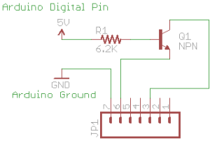
What is a digital out pin?It’s a pin that can supply 0 Volts (off) or 5 Volts (on) depending on what we tell it to do. Below is a circuit which shows how everything is connected in a normal transistor to make it act as a switch. The resistor (R1) is connected to the base of the transistor. The Motor is connected to the collector and the arrow on the transistor (Q1) indicated the emitter.
Take note of the 6.2K resistor, this resistor is a value that you will need to calculate when connecting to a NPN transistor, normally you need to input a certain amount of base current to make a certain amount of collector to emitter current pass through, it’s normally a 1/10 ratio, e.g 1mA will pass 10mA through the transistor if you are using it as a switch.
In this case, you can use Ohms law to calculate the current it would be 5 volts / 6.2K = 0.8 mA will be passing through the transistors base which equates to 8mA passing through the motor and transistor. Lets say this example motor is small that it only needs 20mA to run and 50mA is the stall current. We would place a 1K resistor to let 50mA flow. (5v / 1K = 5mA, 5mA x 10 = 50mA)
Now since I’m using a Cycbot’s robot controller my situation is very unique, you can actually touch both Motor 1 Forward and M1+2 Ground with your hands and the motor spins, this suggests that it doesn’t matter the too much on current that is passing through. My body’s resistance is around 325K when touching both wires with my fingers, you can calculate the current it would be 6 volts (the motor’s voltage) / 325K = 0.01875 mA which is very low.
Below is my circuit that I will be using because of my Cycbot’s motor controller.
Notice how the Arduino’s ground is connected to the ground of the motor controller, this is very important because the 5 volts we put in the transistors base has to go somewhere and so we connect the Arduino’s ground to the motor controllers ground. If we were to connect the ground directly to the transistor in my case funny things start happening, like both motors turn on when only one should be on, so you want to connect the ground to the very last point of the circuit that is ground (if that makes any sense).
Now when we add in the total 4 NPN transistors with the 4 resistors we get the circuit below.
So in order to make both motors go forward we would apply 5V to Arduino Digital Pins 2 and 3. For reverse we use Digital Pins 4 and 5. For left turns we use 4 and 3 and for right turns we use 5 and 2. Simple huh?
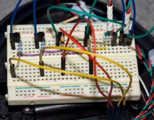
Now go ahead and put all this on your bread board like below.
Now we get into the Arduino code part, once again I’m assuming you understand some basic Arduino code or that you’ve done a little programming before.
/*
Motor Tester
Version: 0.1
Author: electricteardown (http://insidegadgets.wordpress.com)
Created: 5/05/2010
Last Modified: 5/05/2010

Use this program to test your motor controller. It will turn on both motors in both directions to test
going forward and reverse and then turn each motor with opposite directions to test turning.

*/

const int motor1Forward = 2;
const int motor2Forward = 3;
const int motor1Reverse = 4;
const int motor2Reverse = 5;

void setup() {
// Initialize the digital pins as an output
pinMode(motor1Forward, OUTPUT);
pinMode(motor2Forward, OUTPUT);
pinMode(motor1Reverse, OUTPUT);
pinMode(motor2Reverse, OUTPUT);
}

void loop() {
digitalWrite(motor1Forward, LOW);
digitalWrite(motor2Forward, LOW);
digitalWrite(motor1Reverse, LOW);
digitalWrite(motor2Reverse, LOW);
delay(1000);

// Forward
digitalWrite(motor1Forward, HIGH);
digitalWrite(motor2Forward, HIGH);
delay(2000);
digitalWrite(motor1Forward, LOW);
digitalWrite(motor2Forward, LOW);
delay(1000);

// Reverse
digitalWrite(motor1Reverse, HIGH);
digitalWrite(motor2Reverse, HIGH);
delay(2000);
digitalWrite(motor1Reverse, LOW);
digitalWrite(motor2Reverse, LOW);
delay(1000);

// Turn Left
digitalWrite(motor1Reverse, HIGH);
digitalWrite(motor2Forward, HIGH);
delay(2000);
digitalWrite(motor1Reverse, LOW);
digitalWrite(motor2Forward, LOW);
delay(1000);

// Turn Right
digitalWrite(motor1Forward, HIGH);
digitalWrite(motor2Reverse, HIGH);
delay(2000);
}
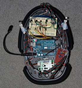
A picture of the robot (ignore the red breadboard and sensors) and video showing the Arduino running this code is below.




[…] you haven’t already, it would be a good idea to take a look at Building a Small Robot: Part 2 – Moving Forward as I explain the use of transistors. Also we will be using a easy to use circuit simulator program […]