Lets begin with Part 3 in which I’ll hook up the ATtiny85, program the simple LED blinking test, take it away from the Arduino, run it on a 9V battery and also how we are actually using the thermistor to calculate the temperature.
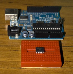
Firstly we’ll visit the website I gave in the first part, which shows us how to hook up the ATtiny85 to the Arduino so the Arduino can program it. Here is a mirror of the site and download files in case it’s down: HLT wiki Arduino A Ttiny 4585_files
We choose from the Arduino program to open up the ArduinoISP sketch which is below the “8. Strings” selection. Now just upload that to your Arduino.
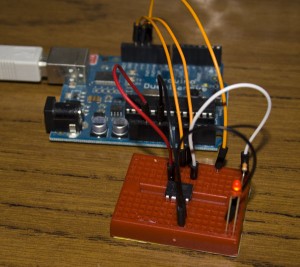
Next hook up the ATtiny85 to the Arduino, select the “Blink” sketch and make sure you choose your board correctly; for me it’s the “ATtiny85”. Remember to change the pin 13 to 0 then upload. Now if you just went off by the website you won’t actually see it blink. After checking it all out, the reset of the ATtiny is connected to the Arduino and on mine it read 0.84V. I took the reset wire out and then it started blinking!
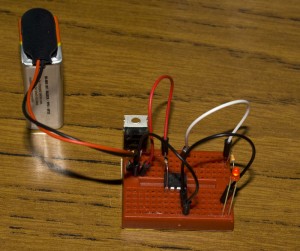
Now we remove it all away from the Arduino’s power, stick in our 5V voltage regulator with a 9V battery for a test. Also you should stick a 10K resistor from VCC to reset so that it doesn’t float all over the place.
It works :), we now have a stand alone ATtiny85 running some code.
I thought I’d stop here and explain a bit more about the thermistor; how we use a voltage divider to make the thermistor work because I learnt something from it too.

From the Arduino Thermistor page, the schematic shows the 10K thermistor and another 10K resistor. This is what is called a voltage divider, because of how resistors work, if you have 2 resistors of the same value in series the voltage drop on both is exactly the same. So 5 Volts / 2 resistors gives us 2.5 Volts; each resistor has a drop of 2.5 Volts. Now we can just probe in-between the resistors and get 2.5 Volts, simple no?
What happens if our 10K thermistor drops to 5K? We use the formula as Vout = Vin – ((R1 / R1 + R2) * Vin) which would be Vout = 5V – ((5K / 15K) * 5V) and that leaves us with 3.33 Volts that will be detected by the Analog In pin.
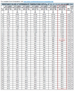
Now if you’re like me what you’re probably thinking is that the 10K thermistor’s maximum value is actually 10K, so it can vary between 0K and 10K… which is actually wrong! I took a look at the datasheet for a 10K thermistor in my case the Vishay one and if you look on page 10 it actually shows you the different resistance values at different temperatures.
So it turns out that when it says 10K thermistor that 10K is the value given at 25C, ah ha! We can now easily calculate at which resistance what our analog in voltage will be but we don’t need to as it’s already been done for us.
That wraps up this part. I now have my own simple 2 Wire protocol up and working which I’ll explain in the next part, I’ll provide a schematic of how things look plus a demo of it in action! See you soon.


