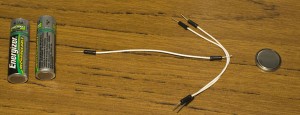
Welcome back! In this part we’ll explore how we can reduce our power consumption which will allow us to move from 2 AA batteries to a 3V coin cell.
When the whole circuit is operating in logging data mode and at 2.68 volts, it’s taking up 1.06mA. First off this 1mA is much lower than our assumed 2-3mA because we are running at 3V instead of 5V, less voltage means less power consumption. Using the Battery Life Calculator with a 240mAh battery it gives us a estimated battery life of 8 days. Lets see how low we can get our power consumption to!
Remove constant voltage to thermistor instead re-use data pin
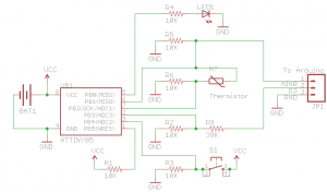
By re-using the data pin to actually enable the thermistor when it’s needed, it reduces power consumption. The only downside is that we use a tiny bit more power when transferring the logged data to the Arduino but that’s not important here. We had a constant voltage on the thermistor which we’ll assume was at 10K so our circuit would also be taking up 0.268mA which is 1/4 of the 1mA total we found being used.
digitalWrite(dataPin, HIGH);
int tempValue = int(Thermistor(analogRead(thermistorPin)));
digitalWrite(dataPin, LOW);
Once we change the thermistor to use the data pin as the voltage source, it will only consume 0.268mA when a temperature recording is actually needed. Once measuring the current when it was 28C we are now down to 0.86mA. Our new estimated battery life is 9.8 days.
Sleeping with the Watchdog timer interrupt
First things first, we will look into the Atmel’s watchdog timer interrupt feature which allows us to put the ATtiny85 to sleep for x amount of seconds/milliseconds, it’s like the delay() function but consumes less power and depending on the voltage you are working from will be less accurate. I’m going to assume that you know a bit about the watchdog timer, if you haven’t I recommend checking my video explaining the watchdog timer! This is the major change which will allow us to save heaps of power.
Let’s begin to make some changes to our code, firstly we’ll add in the two includes.
#include <avr/sleep.h>
#include <avr/wdt.h>
We add in the functions to allow us to set individual bits in the ATtiny’s registers and the watchdog variable.
#ifndef cbi
#define cbi(sfr, bit) (_SFR_BYTE(sfr) &= ~_BV(bit))
#endif
#ifndef sbi
#define sbi(sfr, bit) (_SFR_BYTE(sfr) |= _BV(bit))
#endif

volatile boolean f_wdt = 1; // Watchdog variable
Next we’ll add the setup_watchdog function to delay every 4 seconds. I chose 4 seconds because that’s the highest value that we can divide 60 (seconds) with and get a whole number.
void setup() {
 pinMode(ledPin, OUTPUT);
 pinMode(buttonPin, INPUT);
 pinMode(dataPin, OUTPUT);
 setup_watchdog(8);
}
We’ll add the main sleep code, setup watchdog and the interrupt detection.
// From http://interface.khm.de/index.php/lab/experiments/sleep_watchdog_battery/
void system_sleep() {
 cbi(ADCSRA,ADEN); // Switch Analog to Digital converter OFF

 set_sleep_mode(SLEEP_MODE_PWR_DOWN); // Set sleep mode
 sleep_enable(); // Go to sleep

 sleep_mode(); // System sleeps here

 sleep_disable(); // System continues execution here when watchdog timed out
 sbi(ADCSRA,ADEN);  // Switch Analog to Digital converter ON
}

// Watchdog timeout values
// 0=16ms, 1=32ms, 2=64ms, 3=128ms, 4=250ms, 5=500ms
// 6=1sec, 7=2sec, 8=4sec, 9=8sec
// From http://interface.khm.de/index.php/lab/experiments/sleep_watchdog_battery/
void setup_watchdog(int ii) {
 byte bb;
 int ww;
 if (ii > 9 ) ii=9;
 bb=ii & 7;
 if (ii > 7) bb|= (1<<5);
 bb|= (1<<WDCE);
 ww=bb;

 MCUSR &= ~(1<<WDRF);
 // Start timed sequence
 WDTCR |= (1<<WDCE) | (1<<WDE);
 // Set new watchdog timeout value
 WDTCR = bb;
 WDTCR |= _BV(WDIE);
}

// Watchdog Interrupt Service / is executed when watchdog timed out
// From http://interface.khm.de/index.php/lab/experiments/sleep_watchdog_battery/
ISR(WDT_vect) {
 f_wdt = 1; // Set global flag
}
Now we just need to remove delay() and have it loop for x times until it’s slept for the correct amount of time. We have a waitCounter variable which is incremented after 4 seconds (because of the watchdog timer) and a waitTime variable which determines how many increments of waitCounter it needs before we should log the temperature. For example, for 1 minute logging, the waitTime would be 15 (15 x 4 seconds = 60 seconds), once 15 is reached it logs the temperature and starts all over again.
// Calculate the delay time
 int waitCounter = 0;
 int waitTime = 0;
 f_wdt = 1;
 if (delayTime == 0) {
 waitTime = 5;
 //delay(60000);
 }
 if (delayTime >= 1 && delayTime < 4) {
 //delay((delayTime * 5) * 60000);
 waitTime = (delayTime * 5) * 15;
 }
 if (delayTime >= 4 && delayTime < 6) {
 //delay(((delayTime-3) * 30) * 60000);
 waitTime = ((delayTime-3) * 30) * 15;
 }
 if (delayTime >= 6 && delayTime < 8) {
 //delay(((delayTime-5) * 120) * 60000);
 waitTime = ((delayTime-5) * 120) * 15;
 }
 if (delayTime == 8) {
 //delay(8 * 60 * 60000);
 waitTime = 8 * 60 * 15;
 }
 if (delayTime == 9) {
 //delay(12 * 60 * 60000);
 waitTime = 12 * 60 * 15;
 }
 if (delayTime == 10) {
 //delay(24 * 60 * 60000);
 waitTime = 24 * 60 * 15;
 }

 while (waitCounter != waitTime) {
 if (f_wdt == 1) {
 f_wdt = 0;
 system_sleep();
 waitCounter++;
 }
 }
That’s it, pretty simple when you can just run one function to make your microcontroller sleep. Now when it’s sleeping it’s taking 0.024 mA and jumps to 0.84mA when the temperature is being logged which I’ll be generous and say for 100 milliseconds. The watchdog timer is a bit inaccurate at 2.92 volts, it takes 22 seconds for a delay that should really be 20 seconds. 60 seconds would be 66 seconds, you get drift however exact timing isn’t part of this project so we can ignore this.
Back to our battery life calculator for logging every 1 minute: 240mAh battery, 0.024mA during sleep, 0.86mA when awake, 60 wake ups per hour, 100 milliseconds when awake, gives us 334 days!!! Amazing!
If we were sleeping forever and never waking up, the maximum battery life would be 354 days so we are pretty close to that. For arguments sake, the battery we put in would probably be a little drained as it’s being sitting in the shelf. Say it has 180mAh, the life would be 251 days, not too bad at all.
Change our all of our pins to inputs
We can actually save just a little bit more power by setting all of our output pins as input pins because input pins demand less from our circuit. We have ledPin and dataPin as outputs, so we will change these to inputs before we sleep and back as outputs are we are done sleeping.
void system_sleep() {
 pinMode(ledPin, INPUT);
 pinMode(dataPin, INPUT);

 cbi(ADCSRA,ADEN); // Switch Analog to Digital converter OFF

 set_sleep_mode(SLEEP_MODE_PWR_DOWN); // Set sleep mode
 sleep_enable(); // Go to sleep

 sleep_mode(); // System sleeps here

 sleep_disable(); // System continues execution here when watchdog timed out
 sbi(ADCSRA,ADEN);  // Switch Analog to Digital converter ON

 pinMode(ledPin, OUTPUT);
 pinMode(dataPin, OUTPUT);
}
Personally I couldn’t see any change in current, but then again I only had to change 2 pins, so if you had a more demanding circuit or more pins I’m sure it would help.
Change the LED resistor to a higher value
Another thing we could do to reduce just that extra bit of power when we are pushing the button the set the delay time or to turn on the logging is to increase the resistance of the LED resistor. I tried a 10K resistor instead of 330 Ohms for the LED I used and it only used about 0.25mA in lighting the LED instead of 1.9mA. The LED was still pretty visible so it’s worth doing, I mean who needs a super bright LED right?
Here is our new updated schematic and here is the latest version v1.2: Standalone_Temperature_Logger_ATtiny85_v1.2
This concludes part 7, we now have everything needed to build a PCB and give this project a test in the real world. In the next part I should have the PCB ready to go 🙂


