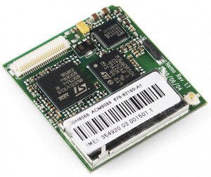
I’ve been looking at GSM modems and wondering how I could integrate them into my projects, they are around $50 or so (Sparkfun) to play around with. I’m thinking of using them to send an SMS when an alert is detected for a sensor, this could be a smoke detector, intruder alarm, temperature rise, etc. All you would need is a pre-paid SIM card and some credit to last a few months.
With everything, I want to use something that I already have and in this case I have some old mobile phones. It’s crazy to think that you can buy new cheap mobile phone now for around $26.
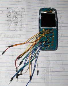
One of the old phones I have is a Nokia 3120. I’ve read there is a MBUS/FBUS protocol which you can use to send or receive SMS’s however my attempts to send any data to the phone fell on deaf ears, I could probably figure out what I should be sending if I had a data cable to sniff the traffic. So I was left with the only thing I could do, wire up the keys and make our MCU press them for us.
Wiring up the Nokia phone
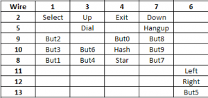
Luckily I didn’t need to wire each key as there were connections between multiple keys, kind of like how a keyboard works.
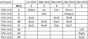
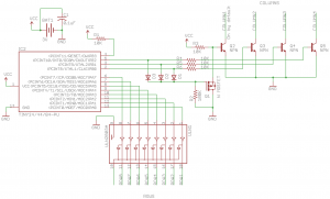
There are 13 wires in total and above are the key mappings. So we need to switch between 8 rows and 5 columns. We can combine the last column to the 2nd last column as there are no buttons in rows 1-5 in the last column which would affect the 2nd last row. I need to use something which could switch the 8 rows and I didn’t want to use individual transistors – a ULN2803A darlington array that I had would do the trick. We’ll need something like that for the columns, I’ll use 4 transistors to switch between them (I would have used another ULN but didn’t have one on me).
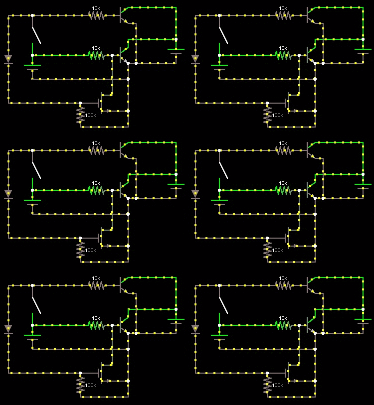
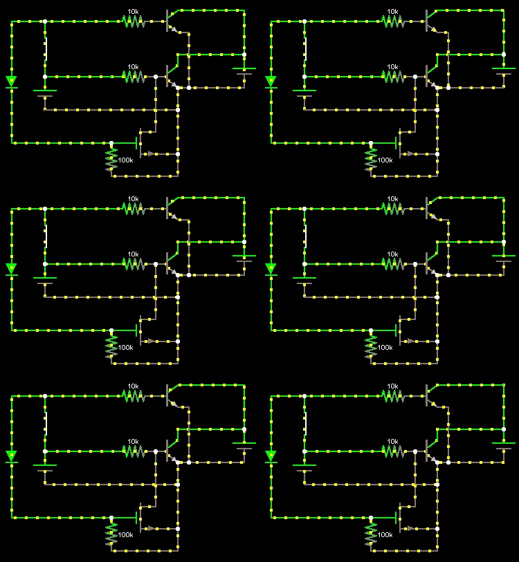
The MCU I’ll be using is the ATtiny24 however it doesn’t actually have enough pins, it’s short by 1 (unless if you use the reset pin which I didn’t want to do). What we can do is have 1 transistor stay on by default and have a Mosfet switch it off when any of the other 3 transistors are turned on.
Above is an animation showing NPN1 (bottom) on by default, we have a switch on the left to simulate turning NPN2 on.
And now we have NPN2 (top) turning on, it turns off NPN1 because the Mosfet turns on. We have the diode in place so that we can use this for the other transistors and not have the transistors turn each other on.
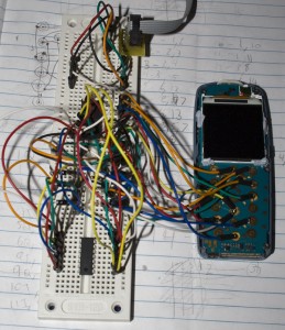
Here’s the result when connecting everything up.
There are quite a bit of parts needed just to have always on transistor functionality. I’ll be looking at removing these extra parts once I can get my hands on an ATtiny261 as it has 15pins that can be used.
Code
Now lets dive into the code.
// Defines which input line to enable on the darlington array and which transistor to activate to ground
// E.g 52 = Enable output 5 (PA4) in darlington array and activate transistor 1 (PB0)
#define buttonSelect 11
#define button2 31 // abc
#define button3 41 // def
#define button1 51
#define buttonUp 12
#define buttonDial 22
#define button6 42 // mno
#define button4 52 // ghi
#define buttonExit 13
#define button0 33
#define buttonHash 43
#define buttonStar 53
#define buttonDown 14
#define buttonHangup 24
#define button8 34 //tuv
#define button9 44 //wxyz
#define button7 54 //pqrs
#define buttonLeft 64
#define buttonRight 74
#define button5 84 //jkl
We use defines to define which button corresponds with which output on the ULN2803A to enable and which transistor to turn on.
// Letter to button presses array
// { Button to push, Number of times to push }
byte letterTobutton[26][2] = {
{button2, 1}, // A (press button2 one time)
{button2, 2}, // B etc
...
{button9, 4}, // Z
};

// Number to button presses array
byte numberTobutton[10][2] = {
{button0, 2}, // 0
...
{button9, 5}, // 9
};
We can use an array as the ASCII character set for A-Z and 0-9, we list the button that needs to be pressed and how many times it needs to be pressed (e.g to get the C character as you know you need to press button2 three times).
prog_char smsMessage[] PROGMEM = "hi this is a test sms which is typed using the keypad. by insidegadgets.";
prog_char mobileNumber[] PROGMEM = "0412345678";
Since the ATtiny24 has only 128 bytes of SRAM, it might not be enough to send a long pre-defined SMS so we can use PROGMEM to store our string where the program memory is, we have 2K (minus our code size) to work with.
int main(void) {

  setup();

  // Set Outputs
  DDRA = 0xFF;
  DDRB |= ((1<We set up our outputs - all pins except the reset pin and then we call the sendSMS function.
[code]void sendSMS(char *smsMsg, char *phoneNumber) {   // Exit out anything that might be up   pushButton(buttonHangup);   _delay_ms(500);   // Create new SMS message   pushButton(buttonSelect);   pushButton(buttonSelect);   pushButton(buttonSelect);   pushButton(buttonSelect);   _delay_ms(500);   // Parse message   int charAt = 0;   char c;   while ((c = (char)pgm_read_byte(&smsMsg[charAt]))) {     parseChar(c, 0);     charAt++;     pushButton(buttonRight);   }   // Enter phone number   pushButton(buttonSelect);   pushButton(buttonSelect);   _delay_ms(500);   // Parse phone number   charAt = 0;   while ((c = (char)pgm_read_byte(&phoneNumber[charAt]))) {     parseChar(c, numbersPushedonce);     charAt++;   }   // Send   pushButton(buttonSelect); }
First thing we do is exit out of any thing that might be shown on the phone and then press the keys to enter into sending an SMS. Now we need to parse the SMS message, we cycle through each character, call parseChar which will convert the character read into a button press and then push the right button to move the cursor to the right so we can enter in another character more quickly. We do the same thing for the phone number but we pass the “numbersPushedonce” parameter to parseChar to tell it to only push the number buttons once.
void parseChar(char c, byte onePushnumbers) {   // Convert lowercase a-z to uppercase   if (c >= 97 && c = 65 && c = 48 && c = 65 && c = 48 && c       lookupChar = c - 48;
      loopEnd = numberTobutton[lookupChar][buttonPushes];
      buttonPressing = numberTobutton[lookupChar][buttonTopush];
    }

    // If we are in a section that allows numbers to be pressed just once (like dialing a number)
    if (onePushnumbers == true) {
      pushButton(buttonPressing);
    }
    else {
      for (int x = 0; x < loopEnd; x++) { // Push the corresponding button x times         pushButton(buttonPressing);       }     }   }   // Dot   else if (c == 46) {     pushButton(button1);   }   // Space   else if (c == 32) {     pushButton(button0);   } }
The parseChar function firstly converts any lower case a-z to upper case. If it finds any character in the A-Z or 0-9 charset it minuses the start of that charset. This means that for B (66), it would minus 65 to give us 1 and then we can go to our array and lookup the values in position 1 to tell us which button to press and how many times to press it. parseChar calls the pushButton function.
void pushButton(char buttonNumber) {   int npnOn = (buttonNumber % 10) - 2; // If reads -1, don't turn any transistors on as we use the one already on by default   int outputOn = (buttonNumber / 10) - 1;   if (npnOn >= 0) {
    PORTB |= (1<  }
  PORTA = (1<= 0) {
    PORTB &= ~(1<  }
  _delay_ms(100);
}
The pushButton function reads the button to push (e.g. 31 for button 2) and breaks that apart into 3 and 1. We minus 1 and 2 respectively to give us 2 (ULN output to turn on) and -1 (transistor to turn on). We convert these to PB or PA which gives PB2 and -1 for PA however -1 refers to the transistor that’s already on so we skip doing anything with PA. We turn on and off the outputs for 100ms.
Conclusion
It works as expected and can be used for anything you can think of :).
Download v1.0: Nokia_3120_KSS_v1.0
Some improvements which can be made include:
- Use ATtiny261 to remove the extra transistor / mosfet circuit
- Use a ULN2003A instead of 4 transistors
- Use a spare output on a ULN2003A to turn the phone on when we want to send an SMS therefore saving the battery until we need it
- Use the watchdog instead of delay_ms
