Following on from Part 1, we built our op-amp circuit and now it’s time to test it out. I ordered both the LM358 and OPA333 and began by testing the circuit on the LM358 as it was a DIP part.
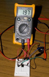
I was powering the circuit from a 3V battery and was seeing something very strange; the output was 1.97V with no load connected.
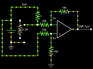
It didn’t seem to match the circuit diagram above.
What I didn’t consider was maybe the resistors need to be a very close value to each other so I measured my resistor’s values and found they were a little different.
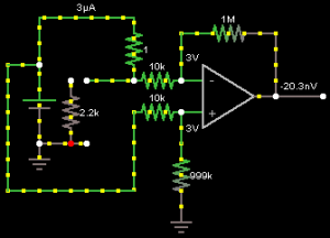
I plugged my resistor values (which were only slightly off – like 9.97k) into the circuit simulation which gave me results of -20.3nv or more probably like 0v, so the small difference in resistor values shouldn’t affect the circuit in the way I was seeing.
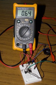
Next I simplified the circuit by have all 10K resistors, so that the – / + inputs should both be equal to 1.5v from my 3v battery so the output should be close to 0V… but it shows as 0.64 volts. I changed the 1 ohm resistor to 10K and the voltage did increase so it was functioning to some degree.
I found that if I powered the op-amp from a higher voltage source (say from 4.5v) then everything worked fine but I wasn’t completely sure what the issue was and didn’t want to use a 9v battery in my design as I want to keep it small.
After spending a few days on this issue, I jumped on the #sparkfun IRC channel and was directed to a page about the op-amp input-output voltage. It says that at the highest output, it won’t reach the supply rail and it will be 1 volt less than the supply rail. This is what I was seeing however it didn’t explain my issue.
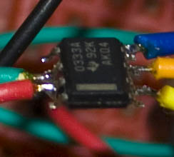
I decided to try the OPA333 with the original circuit as a last resort before surrendering to using a 9 volt battery.
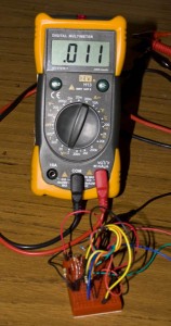
It actually works, it reads 0.011 volts! I think it may have something to do with the “Input Common-Mode Voltage Range” as the LM358 shows 1.5V whilst the OPA333 shows as going -100mV from V- and +100mV from V+ and it says it does rail-to-rail input/output.
This means that 11mV is our baseline; if you remember the OPA333 has an offset voltage of 2uV so what’s causing the baseline is the small difference in resistance values. In our op-amp configuration having a very low offset voltage like 2uV isn’t as important as I thought it would be as we can just cancel it out in software. Once we have a load present, in software we’ll need to minus the load reading by the baseline. Just for comparison, when testing with 5 volts it reads 17mV as the baseline. If the offset voltage was as high as say 1mV that’s when it would cause a problem, we would lose 0 – 0.1V which is 10% of our scale, so our baseline would be 100mV and then we could only measure 0mA to 9mA instead of 0mA to 10mA.
Test the op-amp propagation delay
Now it’s time to test the propagation delay from our baseline to having a load applied because we don’t know how long it will take the op-amp to increase to the expected voltage or to stabilise.
Our ATtiny’s fastest ADC conversion time is 65us, so as long as the propagation delay is lower than that we won’t have any problems. To test, all we do is read the ADC as fast as we can whilst outputting the result via serial and then connect the load.
Let’s test this first with the Arduino with different loads at 3.3 volts. By default its ADC clock is 125KHz x 13 ADC clock cycles which means the ADC conversion is 104us.
| 390 Ohm load | 2.2K Ohm Load | 10K Ohm Load |
|---|---|---|
| 0 | 0 | 0 |
| 0 | 0 | 0 |
| 174 | 34 | 6 |
| 181 | 34 | 8 |
| 184 | 35 | 7 |
So at 104us conversion time plus a few microseconds to send the result through the serial there isn’t a propagation delay noticeable.
Now it’s time to try the Olimexino STM32’s ADC which seems to be around 1us or so and then the overhead microseconds for serial.
| 390 Ohm load | 2.2K Ohm load | 10K Ohm load |
|---|---|---|
| 12 | 11 | 16 |
| 797 | 49 | 46 |
| 1012 | 217 | 56 |
| 1032 | 208 | 57 |
| 1019 | 208 | 56 |
There seems to only be the occasional delay in propagation however it should be less than 65us that we’ll use on the ATtiny.
For the next part, we’ll test this out to save in the ATtiny’s SRAM and once that works we can use an external SRAM via SPI.
