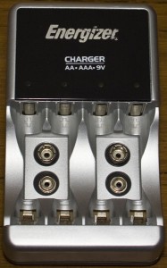
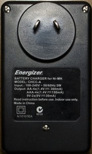
Another quick teardown, this time we open up an Energizer AA/AAA/9V battery charger.
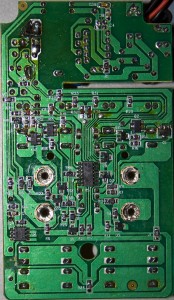
3 screws later and we’re in. At first it looks like a single layer board but on the back there’s a double sided board.
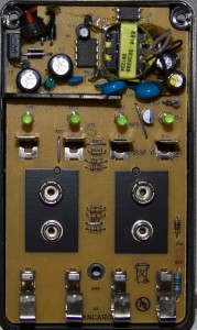
On the top board, we see the AC to DC circuitry with a VIPer12A switched mode power supply (PDF) and there was an application note showing the supporting components which I assume this charger would be using. Apart from that we just have the LEDs to show when the batteries are recharging and the battery connectors.
On the bottom board we have a 2 chips, the middle one is a 8 bit EM78P153 MCU (PDF) whose datasheet seems to be half in Chinese and English and the 4 pin chip which I wasn’t able to identify. The MCU would just be acting as a timer for each battery as from I can see there doesn’t appear to be any ADC functionality on it. There are a few Mosfets/Transistors for each battery connection.


Please can you tell me the value of the resistor located (beside C1) between the two capacitor (on the left to the C9 Blue Capacitor)
Thanks
Hi Ahmed, it looks like a resistor but is actually an inductor with the bands – orange orange brown silver – 330uH 10%.
Thanks alot, its not visible from the up view