Following on from Part 1, we defined the modifications to make to the existing alarm system. In this part we’ll look into the two way communication for the PIR sensors, to be able to turn them on/off wirelessly.
We learned how to use the nRF24L01 module in one way communicate mode so we’ll need to modify that to have two way communication so that the PIR sensor can check in with the alarm system and receive a response back. I have 5 PIR sensors which I’m looking to do this for so the alarm system will need to listen for each one. From here on in I’ll refer to the PIR as the client and the alarm system as the server.
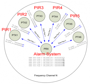
By looking at the datasheet it shows a configuration with one receiver communicating with 6 other transmitters at once. The nRF24L01 has 6 data pipes and when ever a packet arrives, we can check which data pipe it came from. This is useful because we may be in the middle of talking to PIR1 when PIR2 sends a packet, we wouldn’t know it was PIR2 if we don’t check the data pipe. If this happened, we would want to ignore PIR2’s packet and have it retry again later but in my example we only do one receive and one transmit so it doesn’t matter in my case.
For both the receiver and transmitter we need to have these enabled:
- RX_ADDR_P0 as TADDR – for auto acknowledgement
- RX_ADDR_P1 as RADDR – for listening
- TX_ADDR as TADDR – for transmit
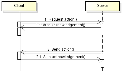
Here is the diagram of communication between the client and the server.
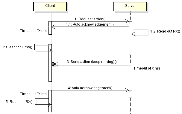
A problem that comes up is a synchronisation between the client and server. After the first packet is transmitted, each side does something – the receiving side reads out the packet and processes it while the transmitter switches to reading mode. But what if the server never sends anything back? Also we would like to save as much power as possible on the client so we can’t just keep waiting to listen to a reply or re-transmitting a packet.
What we can do is make the server the one that keeps listening/transmitting and make the client the deterministic part of the equation. The client would sleep for a few milliseconds until we knew that the server would have finished reading out the RX, then as the server is continually transmitting the action, we wake up from sleep and only need to listen once to receive the action straight away. We also add in timeout counters too in case either client or server times out.
We now have the protocol done, it’s time to move on to the code.
Client side
We add this to the receiving code:
while (!(mirf_status() & (1<<TX_DS))) { // Wait until we receive an ACK back
  _delay_us(250); // Wait the auto retransmit time
  if (mirf_status() & (1<<MAX_RT)) { // If maximum retries reached
    mirf_config_register(STATUS, 1<<MAX_RT); // Reset maximum retries to be able to transmit again next time
    return 0;
  }
}
And this to the sending code:
int waitcount = 0;
while (!(mirf_status() & (1<<RX_DR))) { // Wait until data is ready to be read
  _delay_us(250);
  waitcount++;
  if (waitcount >= 4) { // If we haven't heard back in 1ms, exit
   mirf_CE_lo; // Stop listening
   return 0;
  }
}
In both instances, we only wait a short amount of time.
// Sleep for 1 second
setup_watchdog(T1S);
system_sleep();
turnOffwatchdog();

if (!check_in()) { // Check in with the server
  for (int x = 0; x < 5; x++) {
    mirf_CSN_lo;
    _delay_ms(50);
    mirf_CSN_hi;
    _delay_ms(50);
  }
}

uint8_t check_in(void) {
  // Send a request
  if (!mirf_transmit_data()) { return 0; }

  // Sleep 32ms for the server to read/print out the data
  setup_watchdog(T32MS);
  system_sleep();
  turnOffwatchdog();

  // Receive the response
  if (!mirf_receive_data()) { return 0; }

  return 1;
}
Above is the check in code we use to ask the server what action we should take. If we can’t communicate with the server we just blink the LED. We sleep for 32ms after we transmit the initial data because we don’t really know how much the Arduino will take to read out the data and print out results to the serial window.
Server side
We add this to the receiving code:
int waitcount = 0;
while (!(mirf_status() & (1<<RX_DR))) { // Wait until data is ready to be read
  _delay_us(250);
  waitcount++;
  if (waitcount >= 200) { // If we haven't heard back in 50ms, exit
    mirf_CE_lo; // Stop listening
    return 0;
  }
}
And this to the sending code:
uint8_t waitcount = 0;
while (!(mirf_status() & (1<<TX_DS))) { // Wait until we receive an ACK back
  _delay_us(250); // Wait the auto retransmit time
  waitcount++;
  if (mirf_status() & (1<<MAX_RT)) { // If maximum retries reached
    mirf_config_register(STATUS, 1<<MAX_RT); // Reset maximum retries to be able to transmit again next time
    mirf_CE_hi;
    _delay_us(15);
    mirf_CE_lo;
  }
  if (waitcount >= 200) { //  If we haven't heard back in 50ms, exit
    return 0;
  }
}
In both cases, if we don’t hear back within 25ms, we exit.
RX_POWERUP;
mirf_CSN_lo; // Pull down chip select
SPI.transfer(FLUSH_RX);  // Write cmd to flush rx fifo
mirf_CSN_hi; // Pull up chip select
mirf_CE_hi; // Start listening

// Wait for incoming requests
Serial.println("Waiting");
while (!(mirf_status() & (1<<RX_DR))) {
  _delay_us(250);
}
mirf_CE_lo; // Stop listening

// Packet received, receive/read the client's request and transmit the action
if (process_check_in()) {
  Serial.println("Packet received and reply sent");
  Serial.print("Data received was ");
  Serial.println(data_in[0], DEC);
}
else {
  Serial.println("Packet received - check in failed");
}

uint8_t process_check_in(void) {
  if (!mirf_receive_data()) { return 0; }
  if (!mirf_transmit_data()) { return 0; }

  return 1;
}
As the server all we do is stay in receiver mode and process then transmit the response once a packet is received. We flush the RX in case we received more than 1 packet when we were processing the check in.
So now we can add the other clients to receive data from but as we only have 1 TXADDR to set – what about sending data back? There could be multiple ways to do this, the easiest would be to check the pipe the first packet came from and set RX_ADDR_P0 / TX_ADDR as the pipe it came on, e.g pipe 1 would be clnt1, pipe 2 is clnt2, etc.
But I won’t need to do this because my clients won’t always be listening or transmitting at the same time. This means that I can technically set the same receiving/transmitting address to each client and the server. If there are ever 2 clients that transmit at exactly the same time, the server might auto acknowledge both packets but would only process the first client’s request.
Download nRF24L01_TX_RX_v0.2
This all seems straight forward however the messages are being sent in the clear meaning that potentially anyone could control the clients. This might be the case for the alarm system 433MHz wireless too but is outside of our scope (for now). In the next part we’ll look into how we can secure the communication between the client and server.
Part 1
Part 2: Two way communication for PIR sensors
Part 3: Secure communication
Part 4: Adding on sirens and SMS sending
Part 5: Modifying the PIR sensor
Part 6: PIR PCB
Part 6.5: PCBs arrived
Part 7: See which sensors check-in
Part 8: Building our own alarm system
Part 9: Remote control and attempted improvements
Part 10: Prototype PCBs


