Today we’ll be looking at the BenQ 21.5″ E2200HD LCD Monitor which features a 1080p display, HDMI / DVI / VGA inputs, speakers and a headphone jack. This one stopped working one day, I’ve had it for 8 years so decided to take it apart to see what was wrong.
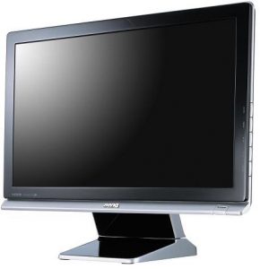
(forgot to take some pictures of it before I took it apart, so here’s a stock image)
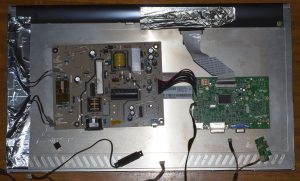
After a couple of tough clips and removal of the stand, we’re in. There was a metal cage holding the power and logic boards but it was just stuck on with some shielded tape, no screws whatsoever which was odd. Powering it up by the power button, I can see the power LED turn on for a fraction of a second, does this 2-3 times before it no longer lights the LED.
Logic board
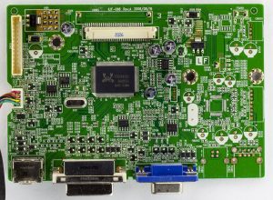
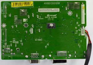
The logic board is a single chip solution, the RTD2482 which supports VGA (RGB), Component (YPbPr), HDMI, DVI and DisplayPort 2A+2H with an audio DAC, infrared controller and supports resolutions up to 1920×1200 resolution. Running from a 27MHz crystal.
There are un-populated connectors on the board, 2 on the top right and 2 on the bottom right, one spot for USB (with a separate power rail for it) and an ethernet connector. The first regulator on the board is a 50117-K 3.3V LDO and second one a AS1117L-12 1.2V LDO, both of which decent heatsink pads which includes the bottom of the board.
We have a few EEPROMs around, 3x ST 24C02 2Kbit, a ST 24C16 16Kbit some of which I believe would be for the display inputs so video cards could identify the monitor and a MX 25L2025 2Mbit serial flash.
Power board
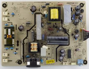
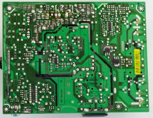
For the power board we have 2 main outputs, the LCD backlight and the 5V for the logic board/5V for the USB port (not populated). There is a beefy 450V 105C capacitor and a few different brands for the other capacitors (Lelon, Jamicon, Su’scon). The SPW-101 transformer seems to have 12.6V and 6.3V taps and to generate the 5V output they use 2x SB1060 schottky rectifiers.
We have the audio output near the bottom right with an Anpec APA2069 stereo 2.6W audio power amplifier (with 32 steps of volume adjustment). The LCD driver is the MPS MP1009 which drives 4 lamps with 2 N mosfets.
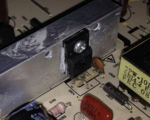
For the high voltage series transistor they wanted to keep the isolation, so they had to bend the middle pin over the isolation slot.
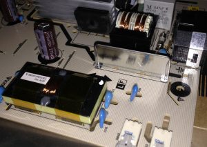
One weird thing is that there is a metal strip between the LCD backlight and near the mains, I don’t know if that is supposed to be a shield or something else, it’s wired to earth, just looks a bit odd.
Troubleshooting
In terms of troubleshooting, all the capacitors looked good so I moved over to checking voltages on the logic board. The 5V input rail seemed good at 4.8V but the 50117-K LDO was giving out 4.5V which was a bit strange, why would you bother dropping 0.3-0.5V but then I checked the datasheet which says the K version should output 3.3V so it’s definitely bad. The 1.2V LDO was ok. No ICs look fried and nothing really gets hot, so there might a chance everything is ok (most ICs on board seem to be rated for 5V).
Swapped out the 50117-K LDO for another 3.3V LDO and the power LED stays on now. I connected it all back together and it’s working fine!


Hey, I’m trying to open a monitor like that right now but im having a big trouble with the clips. Do you remember by any chance how you got this thing to open?
Hi Andrew, I don’t remember the specifics but I started from the bottom where the silver bezel is, used a flat head screwdriver to pry it apart (left some marks) and slowly continued along. The stand needs to be removed, there is a silver plastic cover hiding the screws.
Hello, i have problem with this monitor, after ON show logo, few second black and few second show Desktop and black. Power LED stil ON. I replaced condensator C819 because he wasnt good and C820,C823 preventively. But problem is still the same. 50117-K seems OK too 4,67V/3,20V. When he shows i hear a faint whistling but i dont know where. Can you help me?
I’m guessing the sound is coming from the power supply board?
I would double check all capacitors and test the voltage going into the logic board when it goes black, does it drop out? I’m thinking it probably doesn’t as it would show the logo again, so I think it might be the inverter or bulb.
This video might help with troubleshooting – https://www.youtube.com/watch?v=Dh01ZepjDp0
Hello,
how do you opened the frame?
There are no screws.. The only thing I got lose is the silver bottom plastic trough two holes from down side to open the hooks. There I came not any further with opening.
Thanks
Hi Florian, I don’t recall but I found some steps here, hopefully they help: https://forums.whirlpool.net.au/thread/1155190#r18361561
Thank you very much, did not found this site.
I cannot find any screws. How to open the plastic case?
Hey! I like your guide and it has been helpful this far. But I’m struggling with an issue that I can’t seen to find a solution to anywhere. How do I actually get the metal case off? I unscrewed what I could, but some of the wires won’t disconnect and also I can’t budge the chips in the case out because they are stuck to the holes made for the ports (power, hdmi etc sticking out back). Any idea how to solve this? Thanks
Thank you for the detailed list! I am planning on turning this monitor to an interactive media wall art. There is an USB port on the board which theoreticaly can charge my old android phone with a little soldering.
Hello,
Thank you for sharing. I need to replace one burnt resistor of the power supply PCB, the resistor with the code R831 printed next to it. I’m not experienced and I don’t know the specifications of the resistor to be able to buy the appropiate one in a store. Do you know? Thanks.
Hi Alvaro,
Working on power supply PCBs can be very dangerous.
You can look up the resistor code here: https://www.digikey.com/en/resources/conversion-calculators/conversion-calculator-resistor-color-code
Then measure how long and wide the resistor is and find a similar one here: https://www.digikey.com/en/products/filter/resistors/53
It looks pretty large so it might be a 4W or 2W one looking at the picture.
Hi,
Do you know if and where the service manual can be found and downloaded? thanx.
Is anybody familiar with dead digital inputs on any BenQ’s? I’ve got a BL2420 here which has that, and I found a few posts from people with the same issue on some models, but not anyone who had any interest in getting them repaired.
VGA is the only thing that works, but the monitor appears to ID itself to the computer on the digital lines (DisplayPort/DVI), but gives a “no signal” error. I’ve done their OSD reset, as well as the power-disconnected power button reset. There’s an additional “INIT EEPROM” available in the factory menu, but I couldn’t, for the life of me, figure out how to switch the parameter from off to on. IIRC, the main power lines feeding the mainboard were two or three 5V lines and a 3.3V, which switches on and off when the display is turned on. They all appeared to be working, nothing else shows visible damage and the caps all seemed to have ESR within the normal range.
I’ve held off on snapping it back together in hopes that someone else had this issue and knows what to do.
Thanks! (and thanks for all the other info here)