From our previous part, we started to configure our CPLD to act as an MBC for which we added support for the 512KB Flash we had on hand, tested it with a 512KB MBC5 ROM which worked. In this part, we’ll switch to the 2MB Flash and add support for SRAM.
// ROM writing (audioIn low), pass through a14-15 OR with romBank
if (!audioIn) begin
	highAddress <= ((romBank & 7'h7C) << 1) | (inputAddress[3] << 2) | (inputAddress[2] << 1);
end
Previously when using the 512KB flash we had to add a different method of programming the flash via the audioIn port as the flash commands being sent would conflict with our A14 & A15 lines controlled by the CPLD.
Now that we have the 2MB AM29F016B flash chip, we can remove all mention of the audioIn line from the CPLD and hook up the flash’s WE line to the WR line. After a quick test with a 2MB ROM, it programmed and read back fine and tested on the GBA fine too.
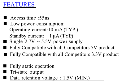
Over to the SRAM now, the chip I’ve gone with is the Alliance 128KB AS6C1008-55TIN which supports a 2.7V to 5.5V supply with a data retention voltage of 1.5V; there isn’t too many SRAM chips that support up to 5V.
It has the usual CE, OE, WE pins but also a CE2 pin which is kind of strange as it doesn’t actually do anything useful, we’ll just tie it to VCC. I decided that I’ll bring the RD / WR pins to the SRAM and just have the CPLD control the SRAM CE line.
Now on to the the CPLD side.
// *** RAM Functions ***
ramCE <= 1'b1;

// 0x0000-1FFF - RAM Enable (Write Only). 0x0A = Enable, 0x00 Disable
if ((inputAddress == 4'd1 || inputAddress == 4'd0) && !inputWR && inputCE && inputRD) begin
	if (inputData == 7'hA) begin // Enable RAM
		ramEnabled <= 1'd1;
	end
	else begin // Disable RAM & RAM CE/OE/WE
		ramEnabled <= 1'd0;
	end
end
Firstly we have to know when to enable the SRAM, by default we’ll just have it pull the CE line high. To enable reading or writing to the SRAM, we have to look for 0x0A to enable and 0x00 to disable at 0x0000 to 0x1FFF (A12 is a 0 or 1), then we set ramEnabled. We also check that WR is low, CE is high and RD is high.
As you might be able to tell, this might overlap with how flashing the ROM is performed, any address that is written between 0x0000 to 0x1FFF and happens to be a 0x0A would enable the SRAM.
It isn’t as bad as a problem as you might think because you only write or read to the RAM at 0xA000-BFFF, an address which we won’t ever access when writing to the ROM.
// Only pass through on 0xA000-BFFF if RAM is enabled
if ((inputAddress == 4'hA || inputAddress == 4'hB) && ramEnabled && (!inputRD || !inputWR)) begin
	ramCE <= inputCE;
	highAddress <= ramBank;
end
As long as the high 4 bytes of the address is A or B, the ram is enabled and either RD or WR is set low, we pass through the CE line to the RAM and set the highAddress variable to be the RAM bank we set.
// 0x4000-5FFF - RAM Bank Number (Write Only)
if ((inputAddress == 4'd4 || inputAddress == 4'd5) && !inputWR && inputCE && inputRD) begin
	ramBank <= inputData[3:0];
end
In order to set the RAM bank, we check if the high bytes are a 4 or 5, WR is low, CE is high and RD is high. We only have to look at the low 4 bytes for the data lines for the maximum value of 0x0F (15) to give us 128KByte (x 8KB) and assign that to be our RAM bank.
I hooked up the SRAM, gave it a few tests and it seemed to be writing/reading back correctly, when the SRAM is powered up for the first time, all the data is pretty random so you have to either zero it out or load your save. I also tried writing a 2MB ROM to it and re-verified the SRAM memory, all was well.
Now that the SRAM works, we need to make it battery backed. The easiest way is to add 2 diodes, one from the 5V to the SRAM and from the battery to the SRAM plus we’ll just need to make sure that CE stays high by default so we’ll add a 10K pull-up. I gave the SRAM a test on a GBA with Warioland 3 and it loaded up the save file without issues.
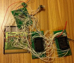
Here’s how it’s all looking.
When testing the SRAM battery it looks like the diodes I’m using aren’t too good as there is about 3uA being fed back into the battery when the cartridge is powered by the Gameboy; it consumes about 4.5uA when the Gameboy is powered off, probably to do with the diodes once again as if I touch the address lines, it drops to 2.4uA. I swapped the diodes out and now it’s only consuming 0.7uA. A typical CR2025 (170mAh) with our 0.7uA consumption would last about 23 years, more than the shelf life of the battery, most SRAM battery backed Gameboy carts seem to last 10-20 years.
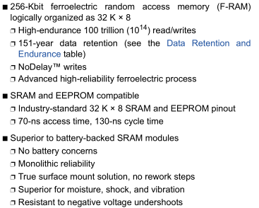
Another option instead of SRAM could be FRAM which doesn’t need a battery backup. They seem to have a retention of 151 years at 85C, the only problem is the price which starts at $25 for 256Kbit (FM28V020). A reader, Jonas advised me of the Ramtron 256Kbit (FM18W08) which is only a few dollars over at Aliexpress so I’ve order a couple and we’ll see how they perform. There doesn’t seem to be a cost effective 128KB FRAM cart but it’s not too big of a deal as not many carts need the 128KBytes apart from ones like LSDJ.
For the next part, I’ll have to make a test PCB with the SRAM plus a spot for a battery so I can then easily test lots of ROMs on it and see which games work and which don’t plus we’ll check out the FRAM to see how that works out.
Parts:
Part 1: CPLD as the MBC and adding Flash as our ROM
Part 2: Adding the SRAM
Part 3: PCBs arrived, Adding some MBC1 support and troubleshooting a few games
Part 4: Adding Multi-game support
Part 5: Using 32KB FRAM and Adding MBC1 2MB ROM Support


