I plan to build a Standalone Temperature Logger with the minimum components as I can, I’ll be using the ATtiny85 and Arduino software to program it. Firstly I’ll have it run on the Arduino to confirm it’s working, then migrate it to the ATtiny85, make it run on battery and make a PCB of it all. It sounds like a simple concept, but I know there’s going to be more to it that meets the eye.
Design Characteristics
- Use the minimum components possible
- Power the project with batteries
- Specify the logging delay time
- Write temperature to EEPROM on-board
- How to extract data from EEPROM
Now lets go through all these design characteristics.
Use the minimum components possible
So I don’t want this standalone temperature logger to be complex or having many working parts. I won’t be needing a real time clock or a external EEPROM or a crystal for the micro, etc. The minimum components I’ve come up with is an ATtiny85V micro-controller with a 10K thermistor, button and LED. Some other components include a battery connector and possibly some header pins.
According to this website it’s possible to program the ATtiny45/85 with an Arduino by having the Arduino act as an In System Programmer (ISP), sounds good. Now I’ve chosen the ATtiny85V because firstly it has 8K flash and the higher 512bytes EEPROM. It has 3 analog inputs and 2 PWM (digital) outputs.
For the component to measure the temperature, I’ve gone with the 10K thermistor that is referenced in the Arduino Thermistor example. It seems that the Thermistor is a Vishay part which has a range of -40C to +125C, something to keep in mind.
Why do we need a button and a LED? Well the single button will be used for starting the logger and configuring the logging delay time (more on this later). The LED will act as a confirmation of our button presses and can blink a few times to show what we have done is confirmed. The LED will be a small 3mm red LED with a diffused lens type to allow for a higher viewing angle.
Power the project with batteries
Do we use AA, AAA or a 9V battery? This is a long question but once you take your time you have an answer, for me it’s AA and I’ll explain why.
Lets start off with a 9v battery, firstly to power the ATtiny85V (note the V), it requires 1.8V to 5.5V. To convert the 9V to 5V we’ll need a voltage regulator, the one I chose is the LM7805.
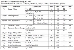
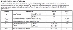
From the datasheet we see the LM7805 can convert 7V to 25V to 5V, excellent that covers our 9V battery. Now lets check the power dissipation.
We see it’s 65C per watt, we’ll assume our circuit takes 20mA (which I’m sure it won’t) and do the calculations: (9V-5V) * 0.02mA = 0.08W of dissipation, so we’ll definitely be fine with no heatsink. Now lets check how we wire it up.
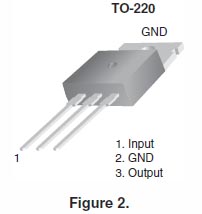
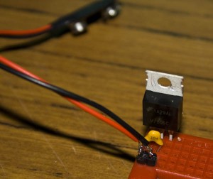
So we connect our 9v battery positive to pin 1 and battery negative to pin 2, then we get out 5v output positive from pin 3 and pin 2 is ground. If you noticed in the Electrical Characteristics it actually gives you a test circuit as: -40C < Tj < 125C, Io = 500mA, Vi = 10V, Ci = 0.1uF. The thing we don’t yet have is the Ci which is the capacitor for the input, they recommend a 0.1uF capacitor and you connect that to pin 1 and pin2.
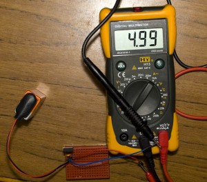
Lets now test the 5V voltage with our multimeter.
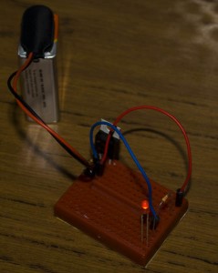
Close enough for me, now time to test a LED.
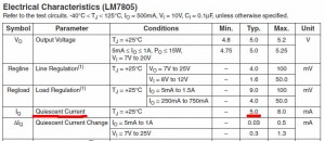
It works! But what we haven’t looked at is how much current does this voltage regulator take up when nothing is connected to it? One would think close to 0mA however it’s not the case, for me it’s 3mA when no load is connected; the datasheet says it’s typically 5mA. This is what’s called the Quiescent Current, the amount of mA the voltage regulator takes when no load is connected.
There are voltage regulators around that do only take close to 0mA however they are expensive and for this project we are going for minimal parts and to keep things cheap. So that’s strike 1 for the 9v battery.
Next thing is how long will the battery last? Ideally I would like it to last a few days and would like to use a rechargeable battery, for 9V it’s typically 175-300mA. I happened to find this battery life calculator website, plugged in the details as 3mA (Voltage Regulator) + 3mA (ATTiny85V + LED [estimate]) current use with a 250mAh battery and got back 1.48 days, not nearly enough, strike 2 and we’re done with the 9v battery.
Let’s move to AA/AAA now, the ATtiny85 supports 1.8V as the minimum working voltage, 1.2v x 2 = 2.4v which is good enough. Lets do the calculations based on 3mA now for our ATtiny85 with the LED rarely on.
AA: 2500mAh @ 3mA = 29.51 days
AAA: 900mAh @ 3mA = 9.44 days
So it’s clear that AA wins this as expected however they are a little larger in size however the days it’ll last is I think worth the extra size.
Specify the logging delay time
I’d like to be able to specify the logging delay time, i.e. time between each temperature reading, without having to re-program the ATtiny, the easiest solution is to use a single button and LED in a different number of ways.
Perhaps when turning on the ATtiny, you can hold down the button for 2 seconds, then the LED turns on to say you’re changing the delay time, something like this? Then you can hold the button down for 2 seconds again and the LED can blink 3 times to confirm your selection?
1 button press = 1 minute delay, 2 = 5mins, 3 = 10mins, 4 = 15mins, 5 = 30mins, 6 = 1hr, 7 = 2hr, 8 = 4hr, 9 = 8 hr, 10 = 12hr, 11 = 24hr
This would mean that when turning on the ATtiny, maybe it’s actually better not to start logging until the user presses the button once or holds it down? I guess that would be good so your previous results don’t get accidentally erased.
Write temperature to EEPROM on-board
So our ATtiny85 has 512bytes of EEPROM on-board, we actually need to reserve the first address to store the logging delay time above, so we have 511 places to log our temperature data. However remember that the range of the 10K thermistor is from -40C to 125C, how do we store -40C to our EEPROM when you can only store the values 0 to 255?
Easy, what I did is take 255 as the upper value, subtract 125 from it and I got 130. So the value 130 is our new 0C temperature, -40C is 90 and 125C is 255, simple. If out thermistor read 30C, it would encode it as 160 (30C + 130).
Now how can we know the last data value, for example, we disconnect the battery or the battery runs out? I originally thought of keeping the a 2 byte address of the last EEPROM address we wrote to however an easier way is just to write 0 to the next EEPROM address. We can do this because we know that none of our temperature values will ever be 0; so we write our temperature value in say EEPROM address 5 and then in address 6 we write 0. The next iteration, we write the temperature value in address 6 and in address 7 we write 0.
How to extract data from EEPROM
For this we could actually use the 2Wire interface. Upon investigation of the ATtiny45/85 implementation on the Arduino that the hlt.media.mit.edu website did, it doesn’t have this functionality enabled. I could go around and start trying to get it working however why not just make my own simpler version of it using 2 wires as well?
My idea is to use 1 wire as the clock and another one as the data out line from the ATtiny. The Arduino would send a CLK of high for say 1 second and then send CLKs of highs/lows each lasting 1 ms. In each of those 1ms CLK highs, the ATtiny would send a high or low according to the EEPROM byte/bit it was reading. 1 byte/8 bits would take 16 ms, so gives us 62.5 bytes/sec which isn’t too bad.
Once the ATtiny reads the 0 in the EEPROM to indicate it’s the end of the logging (as above), it would send 8 bits of lows which indicates 0 and the Arduino would know to stop sending the CLK signal. I’ll have to look into this all a bit more closely.
That’s all for Part 1 and how I believe this project might work, Part 2 will be testing my code on the Arduino which will have all functionality except for the extracting data from the EEPROM, stay tuned!




Hey – great work! I just got an ATTiny85 and I’m looking around for other projects folks have used them for. Keep up the good work!
I believe that the ATtiny85v has an internal temperature sensor; just select ADC4 as the input to the ADC module and you directly read the temperature of the chip. You therefore don’t need the thermister.
Hi, yes you are correct the Attiny85 does have an internal temperature sensor.
A potential downside is that if you wanted to measure fluids it wouldn’t work too well. I was thinking that you could solder the thermistor with the leads intact so it’s a few cm above the board and that was you could put it all in a little box, cut a small hole out for the thermistor and then seal it up.
So yes it’s possible to do away with the thermistor, the only thing is that you would have to calibrate it with either 1 or more calibration points at different temperatures then you can get good accuracy:
“The first calibration temperature is 25°C and the second is 85°C. If +/-1°C accuracy is required, the temperatures where the results are satisfactory range from 5°C to 95°C with three exceptions. The errors at the temperature extremes are much smaller, and the compensation gives +/-3°C accuracy over the whole temperature range.”
Another possible consideration is that you may have to calibrate each individual chip (though probably unlikely to make too much difference):
“The diode voltage is highly linear, but due to process variations the temperature
sensor output voltage varies from one chip to another. Also, the internal voltage
reference used as the ADC reference voltage varies with temperature”
(from Atmel doc8108)
I query this
“Easy, what I did is take 255 as the upper value, subtract 125 from it and I got 130. So the value 130 is our new 0C temperature, -40C is 90 and 125C is 255, simple. If out thermistor read 30C, it would encode it as 160 (30C + 130).”
You are reducing your capability and thus your accuracy. Divide 255 by the 165 degrees spread you want. Each unit on the scale then represents 1.545 degrees So zero degrees equals 62 on the scale . Your 30C example would read 108 on that scale which would be 255/165 X 108 =30C
Your 165 degree spread means readings above 62 are positive and below are negative. There will be more elegant ways to calculate this but for now take your reading and deduct 62 from it . The result is divided by 255/165 or 1.545 . ie 108-62=+46 , +46/1.545 =+30
A reading of 25 would give 25 – 62 = -37 , -37 / 1.545= -24degrees C
Hi, thanks for your comment, I don’t think I would have ever realised that :)! I’ll update the next version so it will have 1.5x the resolution.
[…] http://www.insidegadgets.com/2011/01/03/building-a-standalone-temperature-logger-part-1/ […]
I’ve read that the Attiny85’s internal temp sensor lacks accuracy so really not a good solution for a dedicated sensor.
I would like to know what is advised to avoid corruption to the eeprom due to low voltage condition. Is there a way to protect against that external to the ATTiny? I believe there is also brownout protection that has to be enabled from within the ATTiny which sacrifices some power consumption to enable.
Here’s what Atmel say about the corruption: http://support.atmel.com/bin/customer.exe?=&action=viewKbEntry&id=4
Yes you could enable the BOD with the fuse bits – http://support.atmel.com/bin/customer.exe?=&action=viewKbEntry&id=4
I haven’t had it happen to me yet as far as I know but I know that if it does detect the that voltage is low in BOD mode that it can draw quite a little bit of current in the mode (can’t recall how much).
An external option that Atmel say is to keep the AVR in reset when the voltage is low. An option to explore would be to try the slowest clock startup as 64ms, this could potentially protect you for 64ms if you have a low voltage source or power spike for that long.
hi
i just wanted to ask can your project be modified to include thermocouple input
purpose is same to record temp for period of time than to download it to computer for analysis purpose
Hi Shelendra,
Yes you could modify it for thermocouple input, it appears you would need an interface chip like found here and you would have to adjust the formula to calculate temperature – https://learn.adafruit.com/thermocouple/using-a-thermocouple