Previously we made the GBA TX Cart for the Wireless Gameboy Controller so now it’s time to keep adding more receivers to the project. We have the NES, WiiMote (which should also support the NES/SNES Classic Mini), the N64 plus a Multi-RX adapter which allows you to switch out systems for a lower overall cost.
NES receiver
As I didn’t have an NES to actually test with, I previously had purchased a Mayflash NES/SNES to WiiMote adapter so I should be able to use that to make sure it works correctly.
As the NES just uses 8 clocks instead of the SNES 16 clocks that’s pretty much all that needed to change. A quick verification and test and it was all ready to go, I had even named the PCB “NES/SNES RX” before hand.
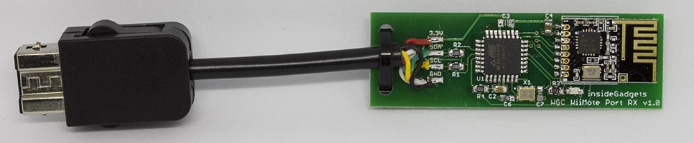
WiiMote receiver
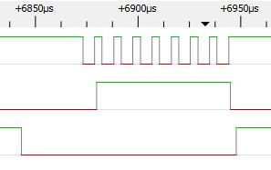
Since I had the Mayflash WiiMote adapter as mentioned, I started looking at it with the logic analyser whilst reviewing different websites to verify their data against what I was seeing with the logic analyser; in some parts they were correct and in other parts they were slightly off.
I won’t bore you with the details but I did get pretty far into it with an ATtiny, up to the point where everything was sent/received in the clear but then it came to the encryption stage. I thought perhaps if I don’t reply to those encryption requests, etc, it may bypass the need but it didn’t seem to be the case so that’s when I decided it was time to look to see if someone had released some code for that.
Eventually I came across the WiiMote Extension Code and the nes2wii project which implemented it, it acts as a classic controller. I choose the ATmega168PB to keep the TWI registers the same as it was implemented and stripped down the nes2wii project so I could add my code.
// Init as a controller
wm_init((void*)classic_controller_id, (void*)cal_data, wiimote_query);
...
void wiimote_query(void) {
	unsigned char but_dat[8]; // struct containing button data
	if (twi_reg[0xFE] == 1) // data format
	{
		but_dat[0] = 0b00000000; // RX<4:3>	LX<5:0>
		but_dat[1] = 0b00000000; // RX<2:1>	LY<5:0>
		...
		wm_newaction(but_dat);
	}
	else if (twi_reg[0xFE] == 3) // data format
	{
		but_dat[0] = jx + 0x80;
		but_dat[1] = rx + 0x80;
		but_dat[2] = 0x7fl - jy;
		but_dat[3] = 0x7fl - ry;
		...
		if (zl) but_dat[7] &= ~(1<<7);
		if (b) but_dat[7] &= ~(1<<6);
		...
		wm_newaction(but_dat);
	}
}
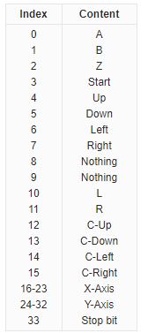
In terms of using the extension code, there isn’t too much to it as it’s all interrupt driven, first you initialise it as a classic controller at start up in which it sends the data format and then you just update the keys as you like.
One problem I did find was that sometimes the buttons would glitch out, if you held it for a while, it would stop being held quickly and then being held again. For example, if you held an item in SMB3, it would release that item by itself.
// Turn off interrupts before resetting key press data and assigning values
cli();

// Reset key presses
left = 0, right = 0, up = 0, down = 0, a = 0, b = 0, x = 0, y = 0,
select = 0, start = 0, home = 0, l = 0, r = 0, zl = 0, zr = 0;
jx = 0, jy = 0, rx = 0, ry = 0;

// Check for key presses
if (kpData & 0x01) { // A
...

// Turn interrupts back on
sei();
Eventually I found that it was the way I was updating the variables, I was clearing all the keys and then updating each one of them. It probably wasn’t spending that much time there but it seemed the glitch happened at least once every 1-2 minutes if not more. The fix was to disable interrupts while updating the keys and then re-enable them, I thought the TWI may have issues by missing packets but it seemed to work fine.
I went back to check out the SNES receiver to see if this issue affected it as I also used interrupts there but it didn’t seem to affect it, maybe it only happens once in a blue moon. I attempted to implement the disable interrupts and re-enable them but that actually made the receiver glitch out, probably because it got stuck counting clocks or similar.
// Check for key presses
uint16_t tempKpOutput = 0xFFFF;
if (kpData & 0x01) { // A
	tempKpOutput &= ~(1<<15);
}
...
// Assign new key presses
kpOutput = tempKpOutput;
Instead of implementing that fix, I just store the new data in a temp variable and then it should only take a few clock cycles for it to assign that temp data to the existing variable. I’ll be updating the other receivers with a similar solution too, just to be on the safe side.
Nintendo 64 receiver
A user had mentioned that I should look into making a Nintendo 64 receiver so I took a quick look and it appears to use 1 data wire like the Gamecube. As I don’t have an N64 and the prices are quite expensive, I purchased yet another adapter – a N64 to USB adapter.
![]()
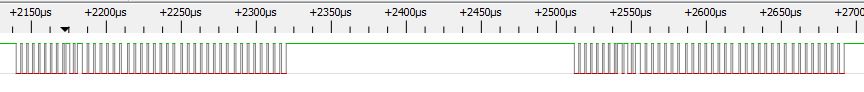
3 weeks later I’ve got the adapter and an extension cord, put it under the logic analyser and could see the single byte requesting data but strangely it was all 0’s, some websites say it should be 0x01 or 0x02 as the request.
Either way, I decided I would send it the data back – 4 bytes containing key press data and joystick movement.
The code was very similar to the Gamecube code except I just stripped out a few parts, it’s simpler. As the N64 controller runs on 3.3V, I simply re-used the Gamecube RX PCB but just swapped the crystal to a 12MHz so we’re operating in the acceptable clock rate allowed for 3.3V but I’ll have a dedicated PCB made for it anyway.
Re-checking the device under the scope, I could see 2 requests now, one for 0x00 and one for 0x01. I checked on the PC and everything seems to be working.
It isn’t available just yet on the store as I’ve just purchased a N64 controller to verify the buttons I’m transmitting are correctly mapped, they probably are but best to be safe, it’ll be another 2-3 weeks.
Multi-RX Adapter
With all the receivers available I thought it might be a good idea to make a base board with swap-able controller connectors which should lower the cost if you have multiple systems that you would like to use.
As I thought of this just as I was implementing the WiiMote RX, we pretty much have to go with the ATmega168PB to make sure the WiiMote side works.
The base board would just have the AVR, 3.3V LDO, nRF24. The adapter boards would have solder pads to indicate which adapter board was connected and the supporting logic. After a little while of combining all the receivers together, it was ready for me to assemble the boards.
I was re-using the same pins for the different adapter boards which worked except for the interrupt pins, it seems that just by placing an if statement to detect say if it was a SNES or Gamecube interrupt, it would be too slow and start glitching out.
I had assign the same wire to 2 different pins to achieve multiple interrupt vectors (actually I went with 3 vectors so if need be I could add another controller adapter in the future if need be – which will now be the N64 receiver). There was a little problem with the adapter board too, had to add another 3.3V LDO for the USB side to work as it should.
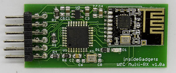
(Base board)
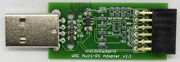
(One of the adapters available – USB)
After the new boards came in, everything tested out well so it’s now available. I’ll just look to add the N64 side to it as well in the coming weeks (after I receive and verify with N64 controller).


