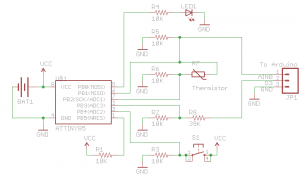
Welcome to Part 9, we have our schematic from Part 7 as below now it’s just time to design and build our PCB. Not a whole lot of content for this post, mostly just pictures.
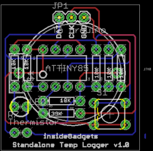
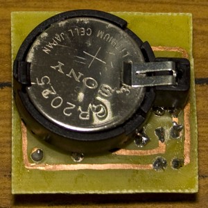
First thing I did was position the ATtiny85 near the center of the board and position the resistors as close to each other as possible. After that it was just a matter of finding where everything else fit. To make the board as small as possible I decided that I would mount the battery on the back of the board.
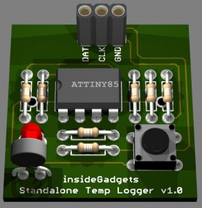
Below is a 3D rendering using Eagle3D of how my board will look.
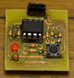
And now how it looks when actually produced.
I tested our my board and yep it all works fine, I have my first prototype! 🙂 In my next version I’ll need to modify the battery holder’s position because fitting it to the PCB was a bit difficult as it was very close to the resistors, this will mean a redesign of the board.
That concludes my Standalone Temperature Logger project and I hope you’ve learnt something during my journey to build this project. I’ll be posting the new version of the PCB and all other useful information to the dedicated project page here: Standalone Temperature Logger
Below is a video showing me testing this project in the freezer and oven:


Nice stuff!
Is there any way to get the temperature logs directly to the laptop, preferably, via USB, without Arduino? That would be pretty cool! I’ve seen a project with attiny85 using AVR-USB or something like that… I guess it would be a nice path for continuing this project.
Yep, that would be something worth doing. I looked at AVR-USB website a month or two ago and it’s a very cool thing that they’ve done.
I think it should be possible to implement it to this project, some things will need to change like the size will be a little larger to accommodate the USB port. There will need to be a small circuit or chip to detect when the USB 5V line is active and then switch power source from the battery to USB (and it would need to be done quickly).
I might start playing around with AVR-USB in the next month or two and see how I go.
meanwhile, could you please give a hint what protocol is used in this Arduino connection? Is this USART? what is needed to get the data?
It’s sort of like I2C (2 wire) but my own implementation of it. It was more for me to learn how to do it myself but I guess it’s quite a good idea for those who don’t have the Arduino. At the moment it won’t work with anything apart from the Arduino.
What my implementation does is it waits for the clock to go low, then sends 1 bit (out of 8 bits) until the clock is high again, then it goes back waiting for the clock to go low, send the 2nd bit, etc. Both sides know that after 8 bits have been transferred that they are to jump to the next data byte. For a greater explanation you can read Part 4: http://www.insidegadgets.com/2011/01/23/building-a-standalone-temperature-logger-part-4/
Thanks for the suggestion of UART, I should really standardise instead of doing my own thing! I think I need to look into the SoftwareSerial library of the Arduino as allows use of regular pins to transmit/receive serial, then yes it could potentially work with UART if you have a UART capable 3V device. If it works then all I would need is really just 1 pin because all that would happen is just a push of the button and it transmits the data and no need to receive anything.
But then again everyone will need a FDTI chip or UART cable, so maybe the best solution is that AVR-USB.
Engineering your own protocol is a nice occupation at least for educating reasons – I believe it’s the best way to learn how things work.
I’m not sure about simplex communications in case of UART. As far as I know it has some overhead traffic (like crc bits and something like that – instead of 8 bits per byte it transfers 11 bits). And yes, it’ll probably require some 232 logic… I asked about UART as it seemed the easiest hack to get data from your logger.
Well. Let’s see, what will come up sooner – you develop a USB version of data logger (I’m sure it would sell well), or I cope building a cheap alternative for your Arduino host. However, the latter is much of a science fiction plot ;-))
hey! I juts thought why don’t you want to give a try to smd? it’d be much smaller!
Myself I haven’t used SMD before. You could use it in this project but I’ll be sticking with DIP because it just means I can re-use the ATtiny if needed and re-program it easily.
It would look like using SMD would make it smaller however the largest component is the battery so it would have to stay the same size (unless of course you use a smaller battery but then of course it won’t last as long). Also then you would need the ISP on the board.