So what good is reading the RAM if we can’t write back to it? This is what we’ll cover in Part 3: Write to RAM.
Writing to the RAM is quite similar to reading the RAM except instead of reading the data pins you write to them. This part won’t be as large as our previous parts because we’re really just re-using our Reading the RAM code. Let’s jump right to the code.
...

  // Initialise MBC: 0x0A
 digitalWrite(3, HIGH);
 digitalWrite(5, HIGH);
 digitalWrite(wrPin, LOW); // WR on
 digitalWrite(wrPin, HIGH); // WR off

 // Write RAM (512 addresses)
 for (addr = 0xA000; addr <= 0xA1FF; addr++) {
   digitalWrite(latchPin, LOW);
   shiftOut(dataPin, clockPin, MSBFIRST, (addr >> 8));
   shiftOut(dataPin, clockPin, MSBFIRST, (addr & 0xFF));
   digitalWrite(latchPin, HIGH);
   delayMicroseconds(50);
All code up to the end of the shifting out the address is the same as in Part 2.
    // Tell MBC to process our RAM request
   digitalWrite(mreqPin, LOW); // MREQ on
   digitalWrite(wrPin, LOW); // WR on

   // Wait for serial input
   while (Serial.available() <= 0) {
     delay(1);
   }

   // Decode input
   byte bval = 0;
   if (Serial.available() > 0) {
     char c = Serial.read();
     bval = (int) c;
   }
We put MREQ to 0 as we’ve done in reading the RAM but this time we put the WR pin as 0 (on) to tell the MBC we will be writing to the RAM. Next we wait until something is received from our Python script. The Python script will read our save file byte by byte and send 1 byte at a time over to the Arduino. Next if there is 1 byte of serial data available (because we just use the if statement once) we store it into our character variable and convert that character into it’s integer value.
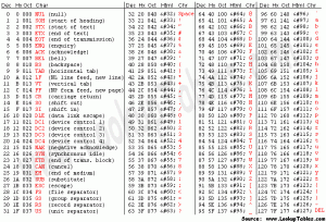
 (ASCII table used from http://www.asciitable.com)
What I haven’t mentioned before is the ASCII table, this table shows the number that represents each character. If we sent over the character “A”, the integer value of that would be 65.
    // Read the bits in the received character and turn on the
    // corresponding D0-D7 pins
    for (int z = 9; z >= 2; z--) {
      if (bitRead(bval, z-2) == HIGH) {
        digitalWrite(z, HIGH);
      }
      else {
        digitalWrite(z, LOW);
      }
    }
    Serial.println("."); // Send something back to update progress
Now we take that integer value 65 (01000001) and read which bits are on and which ones are off by using bitRead; previously we used the AND (&) function but bitRead is simpler. For example, bitRead(65, 7) would correspond to the left most bit (most significant) and would read as 0. Next we turn on the corresponding data pin if that bit was read as HIGH (1) otherwise we set that data pin to LOW (0). Lastly we just print something back to our Python program so we can get a sense of the progress.
  // Done writing this part of RAM
   digitalWrite(mreqPin, HIGH); // MREQ off
   digitalWrite(wrPin, HIGH); // WR off

 }
 Serial.println("END");

 // Disable RAM
 addr = 0;
 digitalWrite(latchPin, LOW);
 shiftOut(dataPin, clockPin, MSBFIRST, (addr >> 8));
 shiftOut(dataPin, clockPin, MSBFIRST, (addr & 0xFF));
 digitalWrite(latchPin, HIGH);
 delay(1);

...
The last thing to do is set MREQ back off (1) and set WR off too (1) and then it’s the same code as Reading the RAM, just to disable the RAM.
Restore the F1RACE save game
Firstly download iG_GBCartRead_Write_RAM_Only and then upload the iG_GBCartRead_Write_RAM_Only_Arduino.pde file to the Arduino.
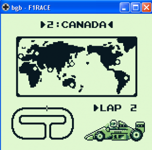
Make sure you have a F1RACE.sav (or change this). I’ve just loaded my save in the BGB emulator to show I’m up to the track “2. Canada”.
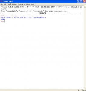
Now run the iG_GBCartRead_Write_RAM_Only_Script.py Python script either by double clicking it or editing and pressing F5.The Python script will open F1RACE.sav and send this save byte by byte to the Arduino. After a few seconds it will show some hashes.
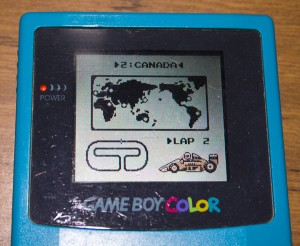
Remove the cartridge, insert into the Gameboy and give it a test, it works!
So that’s it, we now can do everything to the Gameboy Cartridge that we need, read the ROM, read the RAM and write to the RAM 🙂
GBCartRead Part 1: Read the ROM
GBCartRead Part 2: Read the RAM
GBCartRead Part 3: Write to RAM
GBCartRead: Completed
Gameboy Cart Shield released
Buy the Gameboy Cart Shield
Emulating the Nintendo Logo on the Gameboy


Hello, can this be used to save the Gameboy Camera files?
Hi Andre,
Yes it appears someone has been able to get it working, his comment and the changes he made can be found here:
http://www.insidegadgets.com/2011/03/19/gbcartread-arduino-based-gameboy-cart-reader-%E2%80%93-part-1-read-the-rom/#comment-34814
Hi Alex, do you know if to write in the rom (i know you cant write on it, but you can change the chip to a writable other) can be made “as easy” as adapting read from ram to write to ram? I have some AM29F032B-120EI waiting to be installed in some DMG-A02-01 pcbs and I would love to use your GBCartRead and arduino to write homebrew or others games and to have a handmade flashcart but I dont know how difficult will be to get the code to write in the “rom”.
Hi Dan,
I think you could use a little bit of the writing to RAM but flash is different, you have to firstly do a chip erase (or sector by sector erase) then do a 4 or 5 write cycles to program 1 byte of data and then change banks once you reach the end of that bank.
If you check the GBxCart RW project, I have recently added this functionality for a 2MByte Flash Cart which uses an Am29F080B with MBC5 (they swapped D0 and D1 (bit 0 & 1) around on the board which is why data byte 0xAA looks like 0xA9 for example in the code).
A chip erase would look something like this (first line, you would write to address 0xAAA with byte 0xAA, etc)
gb_bv5_flash_write_address_byte(0xAAA, 0xAA);gb_bv5_flash_write_address_byte(0x555, 0x55);
gb_bv5_flash_write_address_byte(0xAAA, 0x80);
gb_bv5_flash_write_address_byte(0xAAA, 0xAA);
gb_bv5_flash_write_address_byte(0x555, 0x55);
gb_bv5_flash_write_address_byte(0xAAA, 0x10);
And to program 1 byte it looks like this:
bv5_flash_write_bus_cycle(0xAAA, 0xAA);bv5_flash_write_bus_cycle(0x555, 0x55);
bv5_flash_write_bus_cycle(0xAAA, 0xA0);
bv5_flash_write_bus_cycle(address, data);
_delay_us(20); // Wait byte program time
Thanks you very much Alex for the fast response! I will try it.
Hi Dan,
I’ve tried to modify your Write_RAM_Only script to work with MBC5 carts (like pokemon red). I tried simply looping over the different banks like you do for the RAM reading code but when I try to play the game after I write to the RAM I get a “game file destroyed” error.
MBC3 not MBC5 I mean.
Also I did a bit more tinkering and found that the only problems seems to be that when I write the the cart the 2nd bank gets shifted forward one byte. All of the other banks look fine.