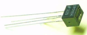
So we’ve got our robot moving in different directions and now we need it to move to the directions we want which is away from walls. We do this using Phototransistors which is sort of similar to a Light Dependent Resistor (a component that changes resistance due to lighting) except Phototransistors actually use infra-red and have two components, the emitter and detector. The emitter well emits the infra-red (which we can’t see) and the detector detects how much of that infra-red is coming back.
Above is a Phototransistor pictured, as you can see it has 4 leads and the 2 components the emitter and detector. The way it works is when the detector receives no infra-red light, it lets the all voltage (in our case 5V) flow through it freely. If we place a sheet of paper and begin to move it closer, more infra-red reaches the detector which in turn reduces the flow of voltage to say 3V now. If you looked at the datasheet you can see the diagram shows the detector actually having the transistor symbol because the voltage it lets through varies depending on the infra-red received and the emitter is pictured as a LED as it just emits the infra-red.
Thanks to RyanM’s schematic we are able to draw this simple schematic that shows how to connect it up:
So how does it all work?
If you read Part 2 you know that you need to use resistors to limit the current that passes through the component that’s connected, if we don’t use a resistor the the fully amount of current will flow from the power source and will damage/blow the component. So we have our phototransistor and it is made up of two components as you can see.
Using the Arduino’s 5 volt supply we firstly limit the current going to the infra-red emitter “LED” (A K) to 22mA using the 220 Ohm resistor. Next we limit the current going to the infra-red receiver “transistor” (E C) to 0.89mA using the 5.6K resistor.
Why is it we need to limit the current to as specified? If you read the datasheet it shows you a kind of “example” on page 2. It lists the test conditions when coupled QRD1114 as current of 20mA to the IR emitter “LED”, the voltage difference between E and C in the IR receiver “transistor” as 5V and the current of minimum 1mA to IR receiver “transistor” which we are pretty close to.
Once we have it all connected, the final step is to connect our Arduino analog pin to the wire between the 5.6K resistor and the “transistor”, why is this? It’s because the “transistor” is a NPN transistor which means that if we connected it up to the end of the transistor (where the arrow goes to) there would be 0 volts all the time. By connecting the wire where we did, we can now read the voltage fluctuations that occur when moving objects in front of the phototransistor.
For example, we would have 5 volts running through the transistor if nothing was in front of the phototransistor, if we had an object 3cm away we might have 4V, then as it got closer it would go down even further to say 2V then 1V and then almost near 0V.
In Arduino terms having 5 volts gives a reading of 1023, 0 volts is 0 and 2.5 volts would be around 511. To read more about this check this link: http://arduino.cc/en/Reference/AnalogRead
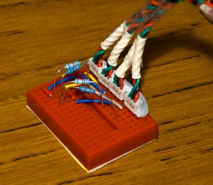
So now we know how to use our phototransistor, lets connect it up. As you can see with mine, instead of soldering wires to it I actually had a few hook-up cables lying around so I’ve used them slide the leads of the phototransistor into the slots, then I broke off some header pins from some old PCBs and used them to connect it up to the breadboard as below.
Now for the code, I didn’t actually need to write any as there is an example that comes with the Arduino program called “AnalogInOutSerial” in which you connect the wire which goes to the Arduino on Analog Pin 0. Once you run it, you monitor the serial connection and you’ll see it print out something like: sensor = 1023 output = 255. Move your hand closer and you’ll see the values decrease. Below is the code by Tom Igoe:
/*
Analog input, analog output, serial output

 Reads an analog input pin, maps the result to a range from 0 to 255
 and uses the result to set the pulsewidth modulation (PWM) of an output pin.
 Also prints the results to the serial monitor.

 The circuit:
 * potentiometer connected to analog pin 0.
 Center pin of the potentiometer goes to the analog pin.
 side pins of the potentiometer go to +5V and ground
 * LED connected from digital pin 9 to ground

 created 29 Dec. 2008
 by Tom Igoe

 */

// These constants won't change.  They're used to give names
// to the pins used:
const int analogInPin = 0;  // Analog input pin that the potentiometer is attached to
const int analogOutPin = 9; // Analog output pin that the LED is attached to

int sensorValue = 0;        // value read from the pot
int outputValue = 0;        // value output to the PWM (analog out)

void setup() {
 // initialize serial communications at 9600 bps:
 Serial.begin(9600);
}

void loop() {
 // read the analog in value:
 sensorValue = analogRead(analogInPin);
 // map it to the range of the analog out:
 outputValue = map(sensorValue, 0, 1023, 0, 255);
 // change the analog out value:
 analogWrite(analogOutPin, outputValue);

 // print the results to the serial monitor:
 Serial.print("sensor = " );
 Serial.print(sensorValue);
 Serial.print("\t output = ");
 Serial.println(outputValue);

 // wait 10 milliseconds before the next loop
 // for the analog-to-digital converter to settle
 // after the last reading:
 delay(10);
}
In the next part we’ll learn how we can use our sensors to control our motors. If you know what your doing you should be able to piece things together yourself, if not wait for my next post 🙂


