Non-Contact Blackout Detector
Feb 4th, 2012 by Alex
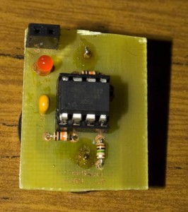
A simple blackout detector using the ADC with a wire and 1 Megaohm resistor. If no AC interference has been detected for 10 seconds (an attempt to detect interference happens every 2 seconds), it blinks the LED and the output pin goes high. You could link the output pin to another device, like a warning alarm, SMS sender, etc.
Features
– Low power consumption, at least 1 year battery life
– Output pin stays high as long as no interference is detected
Specifications
PCB Board: 30mm x 24mm
Voltage: 2.7V to 5.5V
Current used when sleeping: 5uA (When LED is on – jumps to 0.3mA for 500ms and every 2 seconds when ADC is on – jumps to 0.2mA for 60ms)
Operating temperature: -40C to 70C
Download
v1.1 (4 February 2012) – Download
– PCB released
– Added output pin
v1.0 (9 January 2012) – Download
– Initial Release
How to use
Power on the ATtiny25/45/85 and place the coiled wire near AC interference which can be power cables, light switches, fan controls, etc. When power loss (blackout) occurs for more than 10 seconds the LED will start blinking and output pin will stay high until power is restored.
Build your own
Parts Required
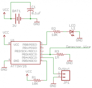
– ATtiny25/45/85 20MHz DIP16 (1) – ATTINY25-20PU/ATTINY45-20PU/ATTINY85-20PU [IC1]
– 10K Resistor 1/8W (2) – [R1, R2]
– 1M Resistor 1/8W (1) – [R3]
– 3mm Red LED (1) – MCL514SRD – [L1]
– 0.1uF Capacitor (1) – [C1]
– 3V CR2032 coin cell (1)
– 8 pin IC socket (1)
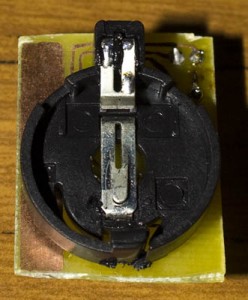
– Coin cell battery holder (1)
– Some coiled wire (optional for better AC interference detection)
Schematic
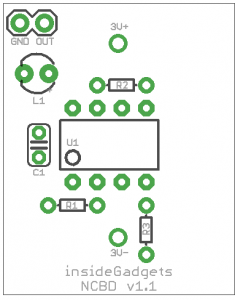
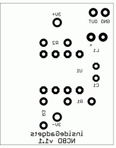
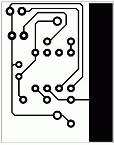
PCB Guide
PCB Ready for etching
Example Project – Blackout SMS Sender
Blackout SMS Sender
Now I thought I’d link this project with the Nokia 3120 Keypad SMS Sender to make a project example named the Blackout SMS Sender. Download the Blackout SMS Sender_1.0.
In the above video you’ll see that the Blackout SMS Sender will SMS me once the power is out and then will SMS me once power is restored with how long the power was out for.
Modifications to the Nokia 3120 KSS were:
- Use Timer0 interrupt every ~0.5 seconds to keep track of the time PB5 has been high for
- Uses delay_ms again as we are using Timer0 to do interrupts and it won’t work well with the watchdog timer
- Uses system sleep IDLE instead of PWR_DOWN as Timer0 won’t wake us up in PWR_DOWN

This work is licensed under a Creative Commons Attribution-NonCommercial 3.0 Unported License.
