Following from Part 3 we tested logging the op-amp’s output, storing the results in the ATtiny’s SRAM and transferring it to the PC. Now we’ll use external SRAM instead of using the ATtiny’s SRAM.
I’m using a Microchip 23K640 SRAM which has a voltage range of 2.7-3.6V. It looks like with SRAM there aren’t many around that can do 2.7-5.5V, this means we won’t be able to power the SRAM from the USB directly when transferring data, we’ll need to use a regulator and level shifters.
Before we integrate the external SRAM to our current schematic, we need to take a look at how to access it, it uses the SPI protocol. SPI is as simple as I2C except that instead of accessing a device by address, you pull the chip select line on the device low and instead of 2 wires you need 3 wires (plus one from chip select). Potentially you could have a lot of SPI devices on the same bus, you would just need a chip select line for each of them.
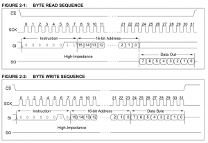
From the datasheet to write to the SRAM we just pull chip select low, send a write command, send the 16bit address and then the data to write. For reading it’s almost the same except we issue a read command and listen for data coming back.
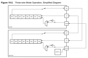
The ATtiny has Universal Serial Interface which allows for 2-wire (I2C) or 3-wire (SPI) built into hardware which we will take advantage of.
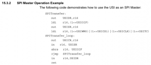
The ATtiny85 datasheet shows us an example of how to use the hardware SPI in assembly.
uint8_t spi_transfer(uint8_t data) {
  USIDR = data;
  USISR = _BV(USIOIF); // clear flag

  while ( (USISR & _BV(USIOIF)) == 0 ) {
    USICR = (1<<USIWM0)|(1<<USICS1)|(1<<USICLK)|(1<<USITC);
  }
  return USIDR;
}
I grabbed the C version of it called spi_transfer from the Arduino playground, all we need to feed in is the data to send the device.
int main(void) {

  setup();

  DDRB |= (1<<ledPin); // SPI CS (LED connected here too)
  DDRB |= (1<<PB1); // SPI DO
  DDRB |= (1<<PB2); // SPI CLK
  DDRB &= ~(1<<PB0); // SPI DI
  PORTB |= (1<<PB0); // SPI DI

  while(1) {

    PORTB |= (1<<ledPin); // CS High, in-active
    _delay_ms(1000);

    // Write 123 to first address of SRAM
    PORTB &= ~(1<<ledPin); // CS Low, active
    spi_transfer(0x02);
    spi_transfer(0);
    spi_transfer(0);
    spi_transfer(123);
    PORTB |= (1<<ledPin); // CS High, in-active
    _delay_ms(500);

    // Read first address of SRAM
    PORTB &= ~(1<<ledPin); // CS Low, active
    spi_transfer(0x03);
    spi_transfer(0);
    spi_transfer(0);
    int test = spi_transfer(0);
    PORTB |= (1<<ledPin); // CS High, in-active

    // If first address reads 123 then blink the LED
    if (test == 123) {
      int x = 0;
      for (x = 0; x < 20; x++) {
        PORTB |= (1<<ledPin);
        _delay_ms(200);
        PORTB &= ~(1<<ledPin);
        _delay_ms(200);
      }
    }
  }
}
We setup the ports, write 123 to the first address, read the first address and if it matches 123 we blink the LED quickly.
I tested it out and the LED blinks quickly confirming that it works correctly. The only problem is that it takes 272us to write 1 byte and we have to do this under 145us. The easiest fix is to increase our clock speed from 1MHz to 4 MHz.
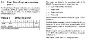
With the 23K640 the default mode of operation is byte mode which only allows us to read/write one byte at a time, we need to write 2 bytes as we have a 10bit ADC value to store.
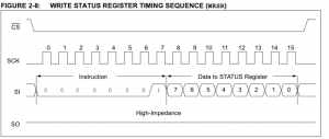
We just need to write 0x40 to the status register to enable the sequential mode.
// Change to 4 MHz
CLKPR = (1<<CLKPCE); // Prescaler enable
CLKPR = (1<<CLKPS0); // Clock division factor 2 (0001)
sei(); // Turn on interrupts
...
PORTB |= (1<<ledPin); // CS High, in-active
_delay_ms(1000);

// Enable sequential mode by writing to the register
PORTB &= ~(1<<ledPin); // CS Low, active
spi_transfer(0x01);
spi_transfer(0x40);
PORTB |= (1<<ledPin); // CS High, in-active
_delay_ms(10);

// Write 123 and 213 to first and second address of SRAM
...
spi_transfer(123);
spi_transfer(213);
PORTB |= (1<<ledPin); // CS High, in-active
_delay_ms(10);

// Read first and second address of SRAM
...
int firstaddress = spi_transfer(0);
int secondaddress = spi_transfer(0);
PORTB |= (1<<ledPin); // CS High, in-active

// If first address reads 123 then blink the LED
if (firstaddress == 123 && secondaddress == 213) {
...
It’s much like before except at the start we jump to 4MHz, enable sequential mode and we write/read 2 bytes at a time. Here is the code: ATtiny85_SPI
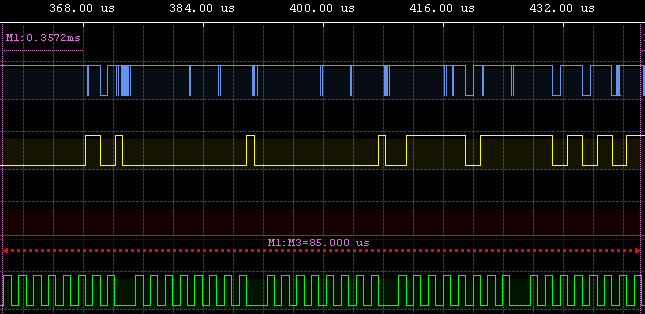
Now it’s down to 85us when sequentially writing 2 bytes, so it’s all good to go.
Our next problem is that we use PB2 and PB1 for V-USB but we need them for SPI. We could make a software SPI however we’ll need 4 pins in total and we don’t have that available with the ATtiny85 so we’ll need to upgrade to the ATtiny84 which has more pins. I don’t have one with me at the moment so this project be put on hold until I can grab one.

