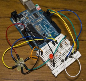
About a year ago I purchased an ATtiny10 with one of my orders but didn’t get to program it because I didn’t have a programmer and didn’t bother getting one. I was looking at Hackaday – it looks like someone wrote up with an ATtiny10 programmer using the Arduino! You program it by pasting the hex file into the serial window.
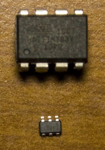
If you haven’t seen the ATtiny10 before it’s really small (above is a picture of it next to the ATtiny85) but has minimal features, program space, SRAM, registers and functions. It can run up to 12MHz, has 1KB space, 32bytes SRAM, no EEPROM and an 8-bit ADC.
The majority of users whom use the ATtiny10 seem to use assembly instead of C; some examples of ASM files can be seen on the link above. I wanted to use C on it, however WinAVR which uses avr-libc doesn’t support it so we’ll have to use AVR Studio.
I’m using AVR Studio 6 and was able to compile for the ATtiny10 without issues, here is a simple blinking LED project – ATtiny10_Blink.
Editing Hex Files
Now when I wanted to use interrupts, it wouldn’t work so let’s take a look into at it (there is probably an easier way to do everything I mention below).
If you include the avr/interrupt.h file it complains about registers issues which is correct because the ATtiny10 has 16 registers vs a normal ATtiny’s 32 registers. Also using sei() didn’t work so what I did was use asm(“sei”) which puts the assembly code sei into our program.
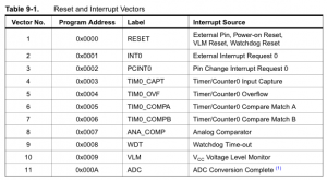
When you use ISR(WDT_vect) – without the interrupts file, it does seem to compile however it doesn’t really do anything. We can check the ATtiny10 PDF (page 36) it gives us the interrupt vectors table – this table always appears on the top of just about every hex file (unless the programmer knows they won’t need certain ones and takes them out) and tells it where to jump to depending on which interrupt occurs.
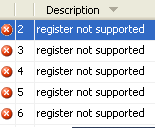
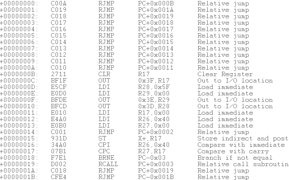
If we check our hex file in AVR Studio 4 to simulate our code, the addresses are all relative to the current position. The first address is when it powers on, it jumps to the address +0000000B but for the rest of the interrupts you see that it points to the same location +0000001B. This shows us that the WDT ISR code we used didn’t work correctly.
Here is the ATtiny10_WDT which I wrote which uses the watchdog timer to sleep for 1 second and then toggle the LED. Below is the code I used for the watchdog timer – you can see it’s just a normal function and not an ISR function.
void WDT_timeout(void) {
  PORTB ^= (1 << PB0);
}
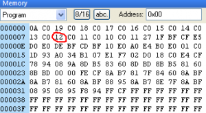
In AVR Studio we can change the code on the fly whilst simulating it. The disassembled hex file above shows the op-codes as C00A for the first location but on the program side it shows it as 0AC0 (bytes swapped).
Since the WDT interrupt is at 00000008, we need to change the 12 in 12C0 to the start location of our WDT interrupt function.
We can check the hex file for where our function starts – it looks to be 00000046 as it has an XOR to PORTB (R25) later in the code. We would change the “12” hex into “3D” hex: 00000046 – 0000008 (the WDT interrupt address) -1 (as our program starts from 0x00).
:100000000AC019C018C017C016C015C014C013C04C
:1000100012C011C010C011271FBFCFE5D0E0DEBF56
:10002000CDBF10E0A0E4B0E001C01D93A034B10743
:10003000E1F725D030C0E4CF8AB7817F84608ABFE2
:100040008AB781608ABF88958AB78E7F8ABF0895F4
:100050008A3008F089E0982F9770883008F0906215
:1000600090648BB7877F8BBF91BF0895F8948BB74F
:10007000877F8BBF81B7877B81BF78940895789401
:10008000089A86E0E5DFD8DFF1DFFBCF92B181E0AF
:0A009000892782B90895F894FFCF84
:00000001FF
When we load up the .hex file directly into a text editor it looks like the above.
But if we modify the ’12’ into ‘3D’ and load it in AVR Studio it complains saying the file might be corrupted.
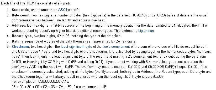
Looking into the hex file format it appears that there is a checksum at the end of each line which is why changing the code didn’t work. I was able to find a spreadsheet from someone at AVRfreaks in which you can calculate the ending checksum.
The second line in our hex file needs to be changed from 1000100012C011C010C011271FBFCFE5D0E0DEBF56 to 100010003DC011C010C011271FBFCFE5D0E0DEBF2B
Now when we open the hex file in AVR Studio it works and has the correct address for the WDT.
The remaining part we need to fix is changing the RET to RETI, so that when we return from the interrupt we enable global interrupts again (sei). We just need to change the 9508 opcode to 9518.
We change it in the spreadsheet too and now have our updated ATtiny10_WDT_Modified – which works on the ATtiny10! (Hex_Checksum_Calculator spreadsheet available too)
This was a long way around to enable interrupts for the ATtiny10 – there has got to be simpler ways of doing this (for one you could just program in assembly) but hopefully this has given you an insight on how we can modify hex files our self and you’ve learned something new from this.
An ATtiny10 might not suit every application and an ATtiny13 may be the better choice if size is not a problem (plus the ATtiny13 is supported in WinAVR/avr-libc).




I would like to thank you for you effort in posting this solution and after many many hours of work and a detailed look into the operation of my ATtiny 10 with your help I have finally got interrupts to work. My only advice is if you could expand your explanation of the addressing of your function as this took me many hours to find my equivalent. I found mine by using the Atmel studio command line disassembler (avr-objdump -d name.elf -S) and trial and error till the function was mapped. I believe the formula to find the jump distance is = (function address)/2 -interrupt address -1.
Regards Mizotor
Hi Mizotor,
I found the start of the WDT function by opening up my .hex file in AVR Studio 4 and when you do that it lets you simulate the code. Because I had almost nothing in my code, I could tell that the XOR was at location +048.
Xor needs 2 inputs – the current pin value and the value to XOR, both of which it loads in +046 and +047 (most of the time if you see RJMP/JMP like as seen at +045, you can assume that the code after that is for another function).
(BTW I was wrong about R25 being PORTB, it’s actually location 0x02 which is PORTB, so you could have your code read PORTB or do something to PORTB and then you will easily know where the start of your watch dog function is)