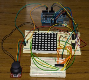
I’ve now gotten a feel for the LED Matrix and have made a Road Runner game for it too, similar to the LCD Road Runner except you don’t have enemies and don’t shoot. I’ve optimised the way levels are stored better than LCD Road Runner so we don’t have to use PROMEM any more. The main highlight is that you can make your own level very easily which I’ll show you how to do near the end of this post.
LED Matrix Road Runner
v1.0 (10 December 2010) – Initial Release with 1 level
Instructions
You control the dot and you need to avoid the walls, you can move in all directions.
Components
- 8×8 LED Matrix – http://www.sparkfun.com/products/681
- Thumb Joystick + Breakout Board – http://www.sparkfun.com/products/9032 + http://www.sparkfun.com/products/9110
- 2 x 74HC595 Shift Registers – http://www.sparkfun.com/products/733
- 1 x ULN2083A Darlington Array – http://www.sparkfun.com/products/312
- 8 x 220 Ohm Resistors
- Arduino Duemilanove or Uno – http://www.sparkfun.com/products/9950
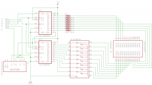
Schematic
How it works
We are using 2 shift registers along with a darlington array to control the LED Matrix rows (Shift Register plus darlington array) and columns (Shift register). By lighting the LED matrix one row at a time, pausing for 2 milliseconds and doing the next row, we are able to light up all of the LED matrix without suffering any LEDs blinking like you might expect to see.
We have a 8 (y) x 16 (x) array to store the which lights are on and which lights are going to be on in the next 8 increments. Basically we paste in 8×8 LED data to the far right of the array and our counter increments which moves the 8×8 LED data to the left by one which gives the effect of the player moving forward.
The joystick controls the players X and Y co-ordinates and maps it to the first 8×8 section of the 8×16 array. Collision detection is calculated by checking if the players co-ordinates matches where the light is going to move.
The levels are packed into a array of bytes to save memory. Each byte represents one row of LEDs because each byte has 8 bits (1 bit for each column of that row), thus we can have 8 bytes and that would allow us to light the whole LED matrix. We use the bit function AND to calculate which LEDs should be on, then map it to a temporary array and copy that across to the 8×16 array.
Make your own levels
Download this utilities and example pack for Windows: led_matrix_level_pack.zip
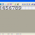
1. Load FastLCD.exe, set the grid size height to 8. You can leave the width as it is or make it shorter or longer (careful not to make it too long). Draw the walls by using the left mouse button and clearing any walls you don’t want by pressing the right mouse button. In the example below we just drew numbers. Save the file as BMP.
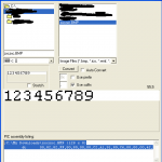
2. Load Bmp2asm.exe, select your BMP file, uncheck “0x Use prefix”, click Convert and then highlight and copy the text outputted at the bottom
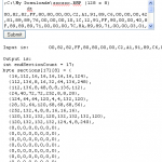
3. Go to my InsideGadgets ASM to Array Converter page, paste in the output text and click convert. Copy the output text.
4. Replace the two variables in the section that says “Change the only the 2 variables below” with the text you copied before.
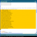
5. Compile, upload and you’re done.


Nice little project. You can improve the display contrast by playing a piece of tinted cellophane over it.
hello,
i am new to Arduino and programming, and thank you for the great tutorials, i have really learned alot. i tried to use the roadrunner just to learn, but the problem i get is that the led that i am supposed to move keeps moving on its own as soon as i upload the code, i tried fixing it but i don’t really understand everything, i am sorry i am just new to this, can you please help me to fix this so i can understand.
i am using the same joystick but a different LED
http://jlbelectronics.com/shop/led-displays/11-kingbright-8×8-led-matrix-red.html
thank you very much
Hi Alex,
Apart from the movement LED, does everything else seem to work?
It sounds like your analogRead for the joystick may be a bit different than my one.
There is an Arduino sketch called AnalogReadSerial where you can read in the analog values when your joystick is at rest and when you move it.
When you have verified your analog values you need to change them in this part of the code:
// Player movement if (playerMoved == false) { sensorxValue = analogRead(sensorxPin); if (sensorxValue > 520 && playerY < 7 && LEDs[playerY+1][playerX] != 1) { playerY++; } else if (sensorxValue < 480 && playerY > 0 && LEDs[playerY-1][playerX] != 1) { playerY--; } sensoryValue = analogRead(sensoryPin); if (sensoryValue > 530 && playerX < 7 && LEDs[playerY][playerX+1] != 1) { playerX++; } else if (sensoryValue < 470 && playerX > 0 && LEDs[playerY][playerX-1] != 1) { playerX--; } if (sensorxValue > 520 || sensorxValue < 480 || sensoryValue > 530 || sensoryValue < 470) { playerMoved = true; } }thank you for the reply, i am not sure if the rest of the code works because movement LED first goes to the far left corner and then it moves to the right corner where it hits another LED and the game resets.
i tried using AnalogReadSerial to find the co-ordinates and in the serial monitor i just get random numbers that start decreasing, even if i don’t move the joystick. i am not sure if this how its supposed to be.
if i dont move it, it starts at 421,421 and then decreases and stays mostly at 370,371
here is the code i used:
void setup() {
Serial.begin(9600);
}
void loop() {
int sensorValue1 = analogRead(A0);
int sensorValue2 = analogRead(A1);
Serial.print(“The X and Y coordinate is:”);
Serial.print(sensorValue1, DEC);
Serial.print(“,”);
Serial.println(sensorValue2, DEC);
Serial.println(” “);
delay(200);
}
hello. sorry to bother you but i fixed it, it turns out my breakout board was faulty thats why it kept moving on its own in the beginning, no the led is fixed.
i got the numbers :
at rest : (516,500)
forward : (516,0)
right : (516,1023)
back : (1023,500)
left : (0,505)
i tried modifying the code to match my number but it didnt work, the led moves in a weird way
thank you
Can you try swapping the X and Y wires around?
thank you very much, it works now but the directions are inverted and at some points the LED doesn’t move, i will mess with the code and try to fix it.
keep it up i am learning a lot from your blog
hello, i am doing Arduino as part of a project i am working on in school, i chose the 8×8 but i dont have much background in programming, i followed ur previous toturial and got the hang of it, but the problem is i dont understand the lines for player movement, if you could please comment and tell me which code does what i would appreciate it.
thank you
if (playerMoved == false) {
sensorxValue = analogRead(sensorxPin);
if (sensorxValue > 520 && playerY < 7 && LEDs[playerY+1][playerX] != 1) {
playerY++;
}
else if (sensorxValue 0 && LEDs[playerY-1][playerX] != 1) {
playerY–;
}
sensoryValue = analogRead(sensoryPin);
if (sensoryValue > 530 && playerX < 7 && LEDs[playerY][playerX+1] != 1) {
playerX++;
}
else if (sensoryValue 0 && LEDs[playerY][playerX-1] != 1) {
playerX–;
}
if (sensorxValue > 520 || sensorxValue 530 || sensoryValue < 470) {
playerMoved = true;
}
}
Hi Craig,
This code just reads the analog values of the joystick – the variables may be a named incorrectly (e.g. sensorx with playerY doesn’t seem right).
If the joystick hasn’t been moved the analog reading was between 480 to 520, so if the reading was under 480 then the joystick was moved to the left and over 520 it was moved to the right. We check if the player “dot” actually moved to the position the user wanted – would it go outside of the LED maxtrix? If so, then don’t allow it. Next the walls have “1” where the dot is, we check that the place we are moving won’t overwrite where the wall is (and later in the code we check if the wall hits us).
Lastly we only want to let the player location be updated when we update the LEDs so we have a playermoved variable to keep track of when 1 movement can be made.
hello,
is there another way to make my own level without using the method you mentioned?
Hi,
You could but not easily, maybe if you re-wrote the method to have the LEDs array as something like so the level creating is easier but takes up more memory.
{ 0, 0 ,0 , 1, 0},
{ 1, 0 ,0 , 0, 0},
{ 0, 0 ,1 , 0, 1},
{ 0, 1 ,0 , 0, 0}
i am really sorry to bother you but i dont really understand this line in the processSectionBytes
if (data & (1<<column)) ? i don't understand the condition, but i think it means move the bits one column at a time, right?
The data variable is loaded with the LEDs for the row we are on (e.g in binary it could be 10101110 to represent the row).
Yes we move the bits to the left and run the AND operator to check which LEDs should be on in that row, going by our example it would go like this:
column 0, if (10101110 & (1<<0)) = 0, the LED is off column 1, if (10101110 & (1<<1)) = 1, the LED is on column 2, if (10101110 & (1<<2)) = 1, the LED is on column 3, if (10101110 & (1<<3)) = 1, the LED is on column 4, if (10101110 & (1<<4)) = 0, the LED is off etc