I’ve previously bought an alarm system from Ebay and have been making modifications to it such as making the PIRs wireless and added wireless sirens. On our last part, we added a way to check which sensors have checked in.
By using everything that we’ve built and modified, it’s now time to make our own alarm system. We’ll be adding in our own PIR, Door sensor, making a slight change to the Siren and modifying the Server.
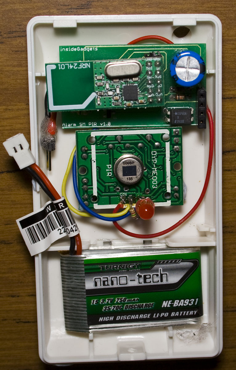
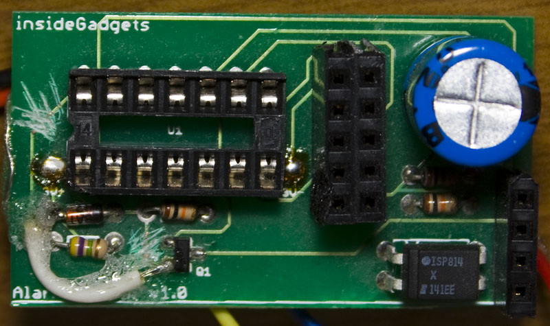
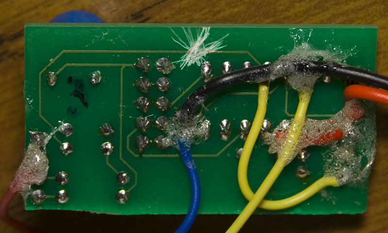
PIR Sensor
I was thinking about how I could potentially box up the PIR with the PCB but I found that the PIR module you buy from Ebay fits in nicely to the existing casing, I removed the PIR cover and it works well. I’ll be switching from the 3V coin cell to a 3.7 Li-poly so that the PIR and the PCB will run off this which should last at least a few years.
One down side of running from the Li-poly battery is that after testing I found that the PIR is unstable when the voltage drops to 3.3V the PIR automatically turns on. One thing I should have added a while ago was a way to monitor the battery voltage, so we’ll add that this time and the cut off will be 3.5V. A few cuts on the PCB, adding some resistors, re-wiring and it’s ready to go.
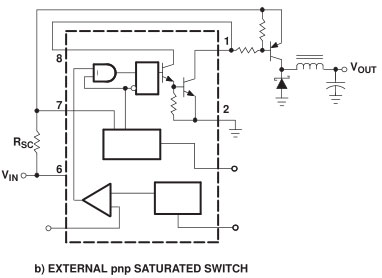
From our last post we looked at the base configuration of a SMPS using the MC34063. In this part we’ll look at adding in an external transistor so that we can bypass the 1.5A peak current limit present on the MC34063.
Above we have the circuit configuration which we can add our PNP transistor on, I’m using the TIP42C.
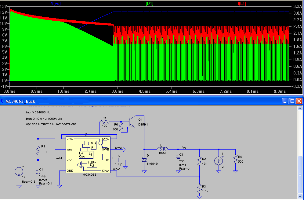
(Voltage – blue, Current though diode – green, Current though inductor – red)
We can test this configuration on LTspice, though one problem when using the transistor is that it gets very hot. For testing I’m using two 100 ohm resistors, so it’s quick to switch on and off. We need an inductor and diode that can handle the current because the 1N5819 diode only can do 1.5A so I choose the Toshiba CMS05-TDE which can do 5A and only has a 0.45V voltage drop. I was able to salvage a decent sized inductor from an ATX power supply.
A little while ago I started looking into CPLDs and because you can have things running in parallel, I thought I could use use one to build a logic analyser which saves the sample to external SRAM. At the moment, I still have the Altera MAXII EPM240 development board with an on board 20MHz oscillator.
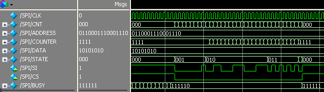
First things first, it’s time to simulate my implementation of the SPI protocol in Modelsim so we can write to the SRAM and then I could use an AVR to read the location to verify the write. Download cpld_sram_write
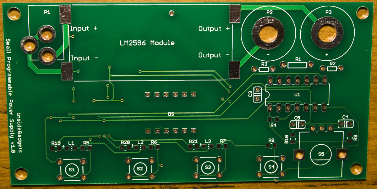
In one of my previous posts, I integrated the LM2596 module into my SPPS project, I’ve been trying out a RAID5 array with 4 hard drives attached to my Raspberry Pi and now it’s time to think about how to power it all. Each hard drive takes about 0.7A on the 5V and 12V rail plus about 1-2A for the Pi so 5V @ 5A and 12V @ 3A but the peak current will be a bit higher when all the hard drives start up; I could use a couple of LM2596 modules but I’d rather build my own.
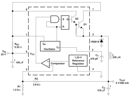
I’ll need something other than the LM2596 that can deliver a bit more power which is where the MC34063 comes along when in the right configuration.
The MC34063 is a buck/boost/inverting switching power supply, you add in a few parts and then it’s good to go. The way a switching power supply works is by using a oscillator at a fixed frequency and a voltage reference with comparator to turn on the mosfet in line with the oscillator when needed, this ensures that the mosfet isn’t fully on all the time.
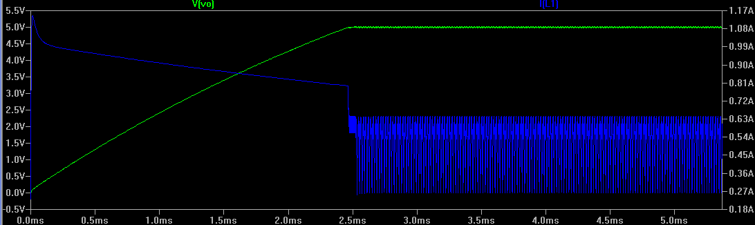
The current from the mosfet passes through the inductor and when the mosfet turns off, the current passes back through the diode and eventually the inductor will charged up to the voltage we require; and once reached, the mosfet only has to provide short bursts of current to keep the voltage stable – you can see this in action in the above simulation (green is voltage and blue is the current passing through the inductor)
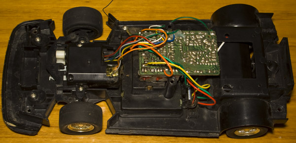
I have had a RC car for about 10+ years (15 years old according to the PCB date code) which I think cost $50 at the time and I thought it would be fun to replace the electronic control boards with an AVR and nRF. It used to run on 8AA batteries and the transmitter on a 9V battery. We’ll be having a look at how things were before and how things look now.
(sneak peak of the end result)
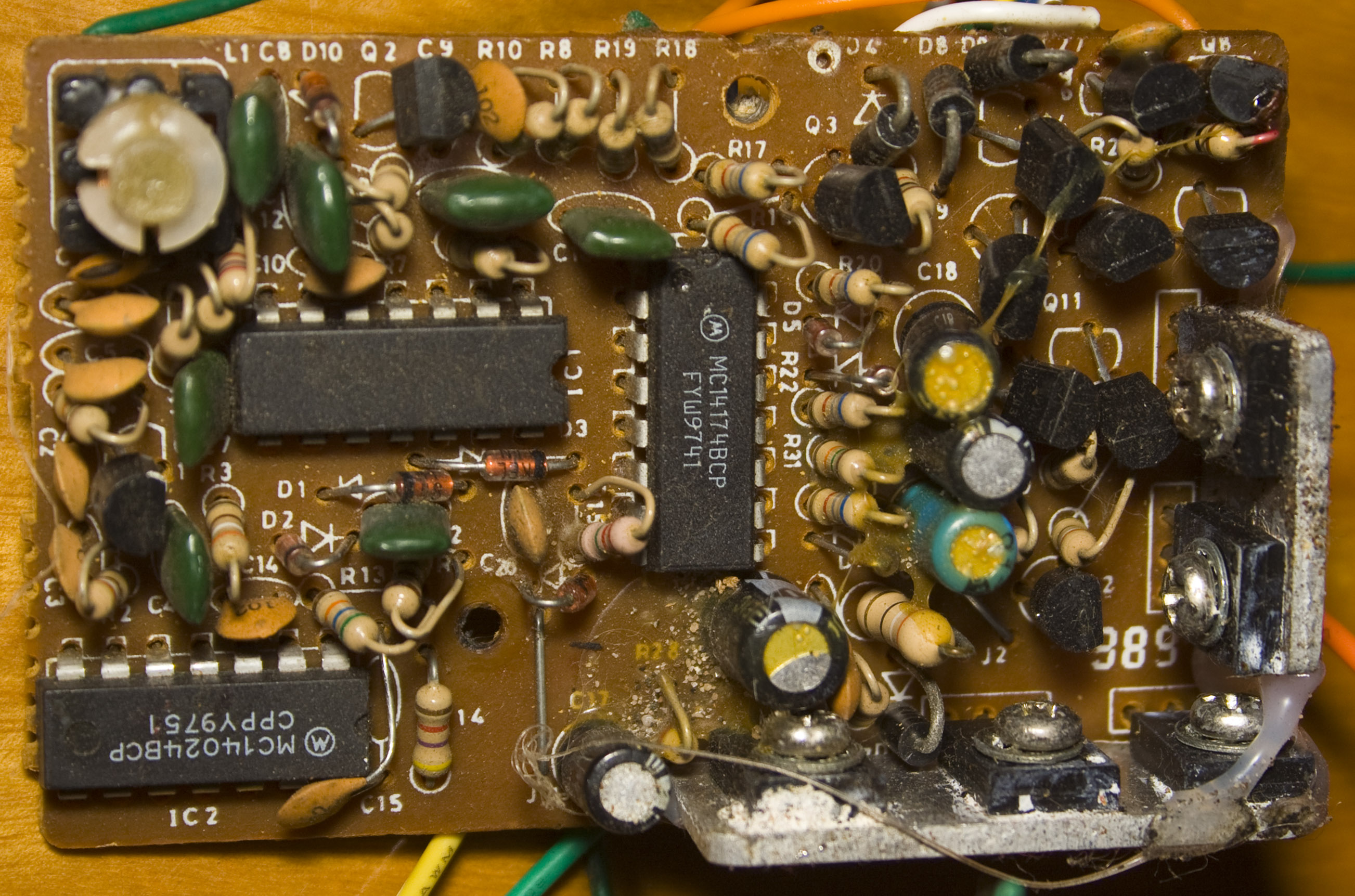
Before – Receiver
Here’s how the receiver looked before, lots of analog parts with a few IC parts like the MC14174 flip-flop, MC14024 ripple counter and power transistors on 2 heatsinks.
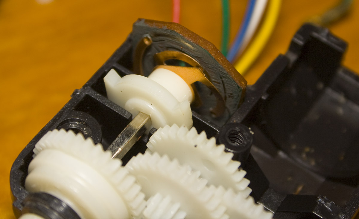
The left/right control is just a motor with what looks to be some form of feedback (with a few wires coming out of it) so it can detect how far to turn the motor.
Following on from seeing nearby nRF24’s on the nRF24 Multi-Network, we’ll now be adding the functionality of forwarding data to other nRFs so they can forward it on to the intended nRF if you can’t reach the other nRF directly. It would be interesting to have a couple nRF’s in a line so that each nRF can only see two others to see how it all performs. I’ve decided to increase the clock speed of the ATtiny to 8MHz to speed things up.
https://www.youtube.com/watch?v=Ht2Y5NRWQmQ
(The left nRF sends a packet to the middle nRF which forwards it to the right nRF and then it goes in the opposite direction)
For the code below – as part of reading packets and processing them, we check if the type is a forward or forward response and if the to address matches our address and it’s a forward, then we send an forward response back. Otherwise if we received the forward response and it was to our address then we’re done. Lastly if the from address doesn’t match our address (i.e we won’t respond to nRFs forwarding our packet back to us) and the TTL doesn’t equal 0, we decrement the TTL and re-forward the packet.
Since other nRFs will be transmitting too in our forwarding scenario, it’s best to wait a little while before re-transmitting so that we are less likely to interfere with other nRFs transmitting the same forward packet.
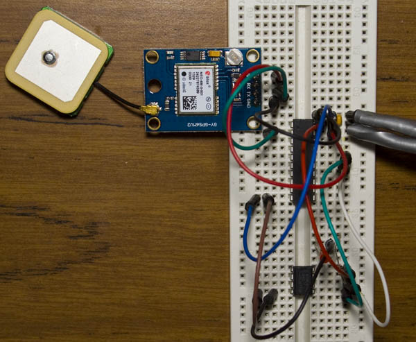
I recently purchased one of those U-blox GPS modules from Ebay for $20 and after downloading the TinyGPS library for the Arduino, it works well once it has valid GPS data (I had to have mine close to the window) plus there’s an LED on the module itself which blinks every second to tell you this, it’s set to 1 PPS by default.
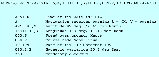
The GPS module outputs it’s data in NMEA format which starts off with a $ dollar sign, has commas in-between values and ends with a line break. At the moment I’m only interested in the longitude and latitude which is in the GPRMC line. My GPS gave 10 bytes for the latitude and 11 bytes for the longitude. If you were travelling all over the world, it’s important to note the N(and S) and W (and E) which indicate whether the number should be positive or negative relative to the equator and prime meridian respectively.
It’s time to compact the size from the Arduino to the ATtiny2313A as it has USART which we’ve used before for sending, receiving is very similar. All we have to do is connect the GPS’s TX to the ATtiny RX, just listen for incoming data, parse that and then I’m logging this to an I2C EEPROM. I’m using a 3.7V Li-poly to power it.
Following on from Part 2, we added a rotary encoder and performed more testing in which we found that since we’re using an LDO (a type of linear regulator), that the mosfet is dissipating the voltage drop, something which I forgot about.
I checked out the LM2596 module again as I was testing designs of making a switch mode regulator like it. On closer examination of it, I found a feedback resistor which I didn’t notice before (next to the 10K por). When removing that resistor I found that re-adding the digital pot this time with a high side resistor of 4.4K allowed me to have a voltage range of 1.8V to 12V however it’s still the case when at the lower voltages it takes more turns of the encoder to increase the voltage, at the higher end the reverse happens but it’s still workable.
Another solution is to use the LM2596 as a pre-tracking regulator as someone mentioned in the comments, so it would absorb most of the voltage drop and then we’d have the mosfet with the op-amp as before – maybe I’ll implement this for the next version.
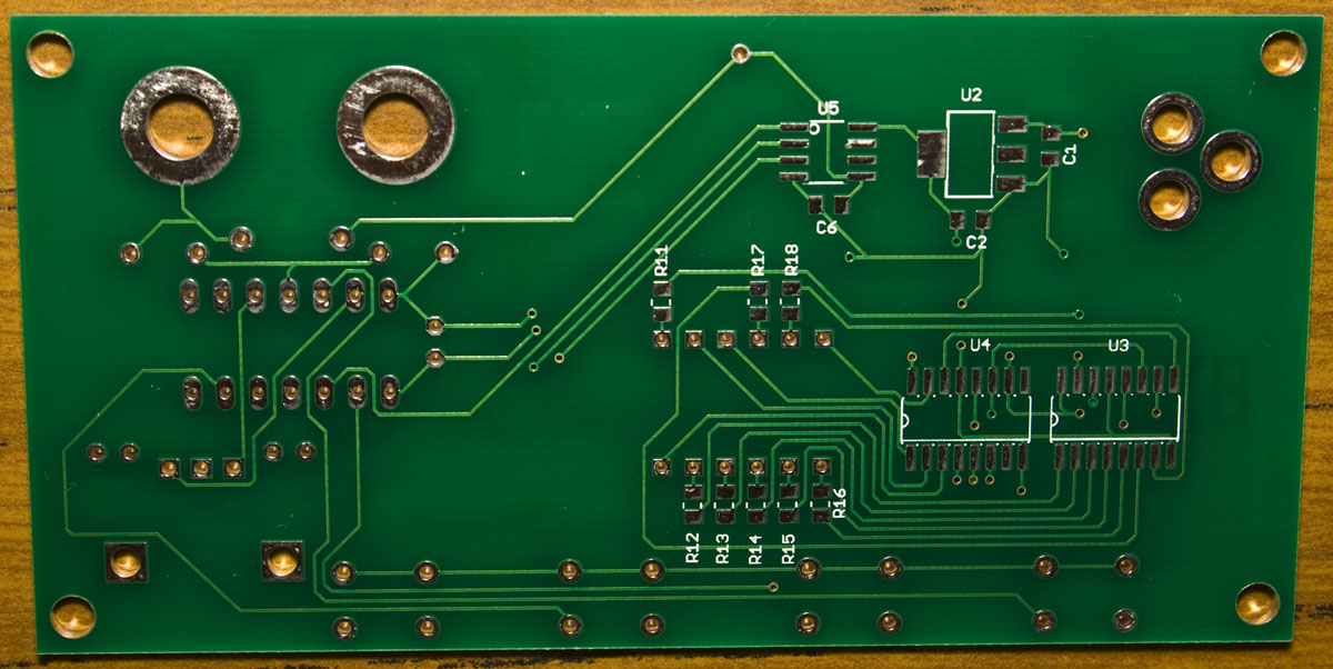
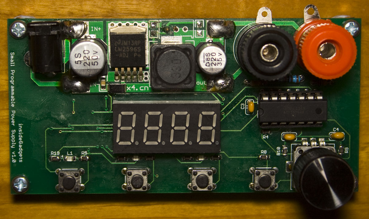
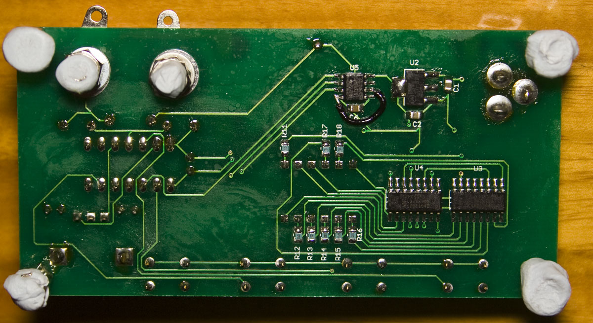
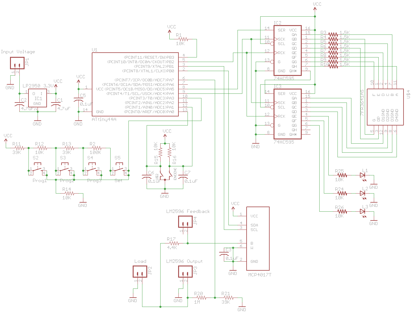
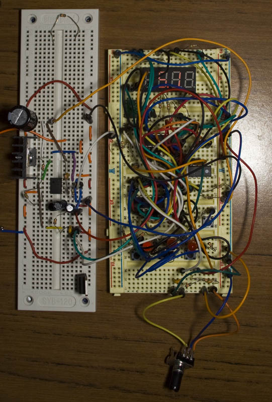
Following on from Part 1, we started to build ourselves a programmable power supply which is working but we’ll be adding more refinements such as adding LEDs for the buttons, using a rotary encoder instead of the voltage up/down button.
(update to SPPS)
The first thing we need to do is use LEDs for each programmable button instead of the 4th segment, we have 4 outputs left from our second shift register, so that’s where we’ll add these LEDs to. Now we can leave the first segment of the LED display blank if it’s under 10V and leave the dot point at the same place. I also moved the set button to be read by the ADC reading the programmable buttons. I’m considering moving to an ATtiny461 to give each button it’s own pin.
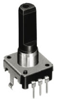
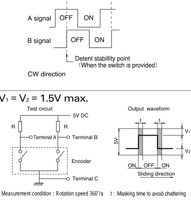
Next we’ll add in the rotary encoder, the way the rotary encoder works is when you rotate the knob it jumps to the next step and when doing so one output goes low before the second output. Rotary encoders can have a different amount of steps, I went with a 24 step one. We can also see the circuit to use above, just 2 resistors from VCC to terminal A and B.
AdvanceVGA – Play your GBA on the big screen! Swap out the LCD for our board, solder some wires, connect 5V USB and VGA and you’re ready to go.
GBxCart RW allows you to backup GB/GBC/GBA ROMs, save or restore game saves and re-write supported flash carts. Mini RW option available for GB/GBC only.
Wireless Gameboy Controller – Use your Gameboy, mGB, GBC, GBA, GBA SP, GB Micro, NDS and NDS Lite as a wireless controller on Windows, Linux, Raspberry Pi, etc, and on your NES, SNES, N64, Gamecube and Wii.