I thought that it’s about time I purchased or made an easy to adjust power supply as all I have at the moment is the LM2596 power supply module from Ebay; one problem is that it’s hard to adjust the 10K pot as you need a screwdriver and another is that it’s not programmable.
(sneak peak)
I’ve chosen the build it yourself route as I don’t think I’ll need more than 1 amp of current. I could just use a computer power supply however I want it to be a bit smaller than that. Another feature I’d like is to be able to program voltages to different buttons.
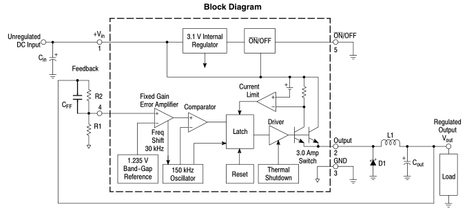
First off, potentially we could adjust the LM2596 using a 10K digital pot however if you wanted voltages more than 5.5 volts then that won’t work out as the digital pot (MCP4017T) I’m using has a maximum voltage of 5.5 volts. If you wanted 0 to 5.5V this would work but I want up to 12V. You can buy digital pots with higher voltage range however they are like $9 each. A quick way around this is to use a resistor divider (like 330 ohm / 10K pot) and use that on the feedback loop however testing this only resulted in a minimum voltage of 2.6V. Depending on the first resistor, when adjusting the pot it lead to a high or low amount of voltage change (e.g 0-5K would only change 1V), so this won’t work out.
I happened to find a document on LDO Regulators and there was an circuit with a P Mosfet with an op-amp and the ability to set voltage reference – the op-amp is constantly adjusting the output compared to the feedback and voltage reference. I’d like a range of 1.8V to 12V, the op-amp should be able to handle that too – an LM358 should do the trick with its 36V max input voltage.
GBCartRead has been updated to v1.4 which now uses C instead of Python to communicate with the Arduino. It’s been a fair while since I last worked on it but I’ve been meaning to do this for at least a year. I found a simple to use RS232 serial library and it’s a bit quicker than the Python version.
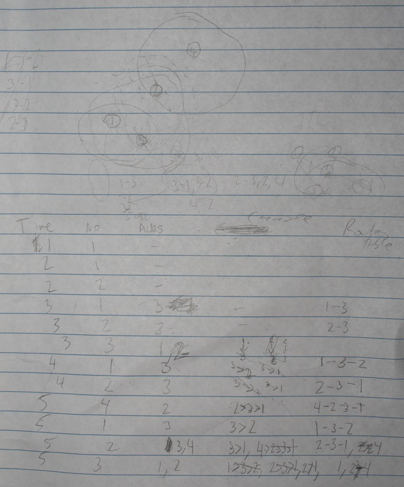
Following on from the initial creation of the nRF Multi-Network, I’ve had a bit more time to re-think the design. I was starting to think of having each nRF request for nearby nRFs, exchange nRFs addresses that each one can see and then have them build a routing table of the possible paths to take to each other.
However that’s a bit too much effort, so instead I’ve decided that if an nRF wants to forward a packet, that it should forward it to all nRFs and the nRFs that receive it should forward it onto all others and so on. For the moment I wanted to test out checking for neighbouring nRFs so they would just reply back to the sender only.
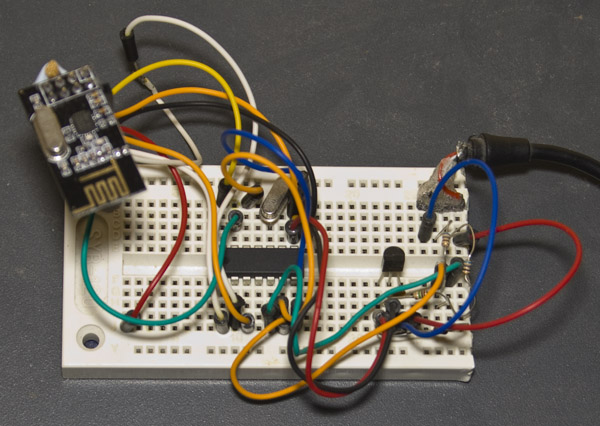
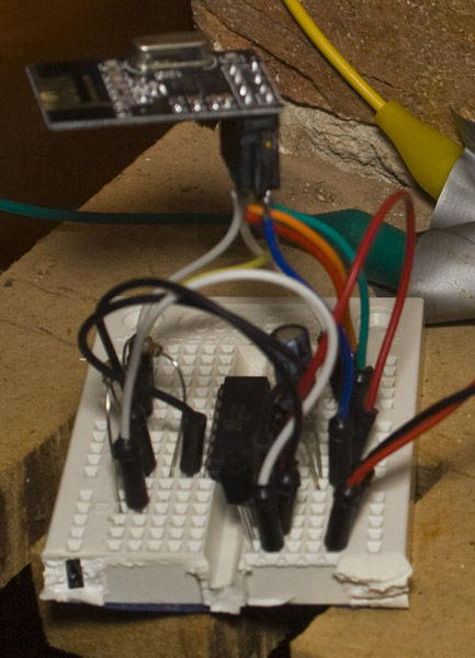
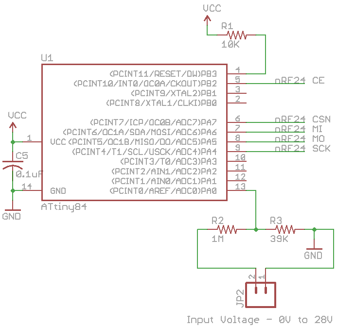
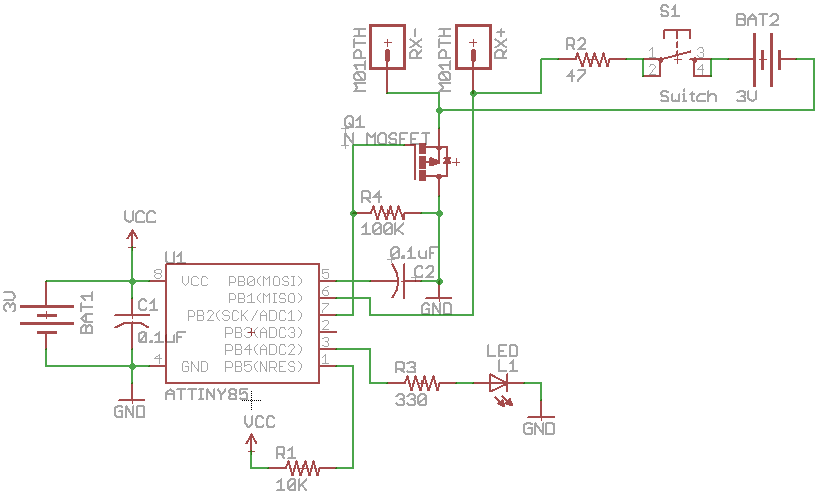
Just a quick simple project I’ve been meaning to do which is to have a nRF24 Wifi module connected to my 12V battery that’s charged by a solar panel and is running the siren of my alarm system. The nRF reader module will connect via USB to the PC and we’ll output the voltage to a file so we can parse the file anyway we like.
For the TX side, we use an ATtiny84 and as we’ve seen before, we use an analog voltage reference of 1.1V and I’ll use a 1M / 39K resistor divider which allows us to measure up to 28V (not that I expect it to go that high). We’ll send the voltage once a second.
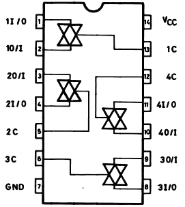
From Part 3, we tested out the INCT on a gigabit network and made some changes to the resistor and capacitors, now that the analog switch has arrived we can try switching between the RX/TX lines to the peak detector. The reason we need an analog switch is that we need to isolate the RX-/+ and TX-/+ lines from each other.
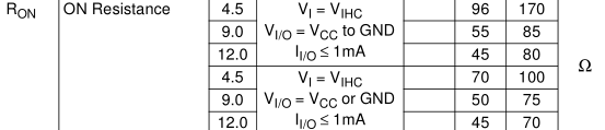
An analog switch is just that, a switch which joins two wires together that is activated by driving the control pin either high or low. I went with the M74HC4066 which has minimum supply voltage of 2V and a quiescent supply current maximum of 1uA at 25C which is pretty good. We also need to keep an eye on the resistance of the switches when they are on, as it will never be 0 ohms, the maximum of 170 ohms should be ok.
When re-testing my current configuration without the analog switch I found that if I removed the one of the two network cables the LED would go off as expected but then a short time later it would flicker a little bit. Checking the scope I found some spikes were occurring and if I reversed the RX-/+ lines the issue went away – so I guess there is a specific way that lines should be connected. Also I found that you shouldn’t leave any control pin floating as that cause the analog switch to draw more current (about 100-200uA).
Whilst waiting for the analog switch to arrive as mentioned in Part 2, I decided to try out a gigabit network switch.
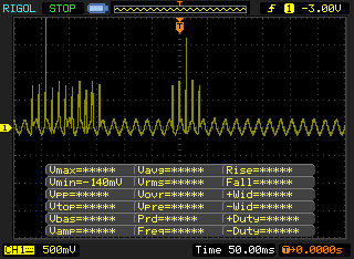
The waveform is faster than the 100Mbit switch but is essentially the same however this time when I connected the diode and 0.1uF capacitor (to form a peak detector) and tried copying data over the network it would slow down and when connecting the 47 ohm resistor the network would drop out.
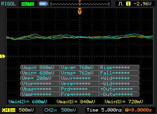
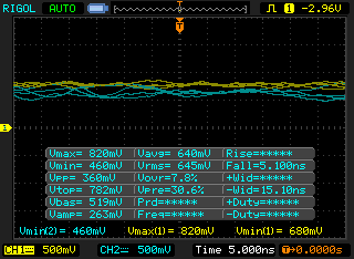
After reducing the capacitor to 10pF it doesn’t drop out anymore and playing around with the resistor I found that a 330 ohm resistor worked well and I also added a 4.7M ohm resistor on the cap. The problem that I found is that the resistor divider’s input (yellow) and output of the peak detector (blue) is a bit noisy, on the left we have how it looks normally and on the right when the 330 ohm resistor is applied, as you can see there isn’t much difference between them – about 100mV average drop.
I had to adjust the resistor divider to be very close to the peak detector output so this is another problem how to adjust the resistor divider to suit the network switch – we can use a digital pot to adjust it automatically however there certain points in the waveform that could incorrectly trigger the LED.
Following on from Part 1, we looked at building our In-line Network Cable Tracer and I was hoping to do a PCB for it however when I connect another INCT to the network cable at the other end, it sometimes didn’t work.
I started playing around with the circuit, removing the capacitor, adding a resistor between AIN1 and AIN0 and tried to use an opamp with it too – none worked well.
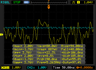
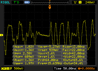
But now that I have an oscilloscope I can actually check how the signal looks, something that the multimeter can’t ever help us with (I removed my earth pin on the oscilloscope plug to make sure nothing blows up). We can see that there is just about -1V and +1V to give 2.38V peak to peak.
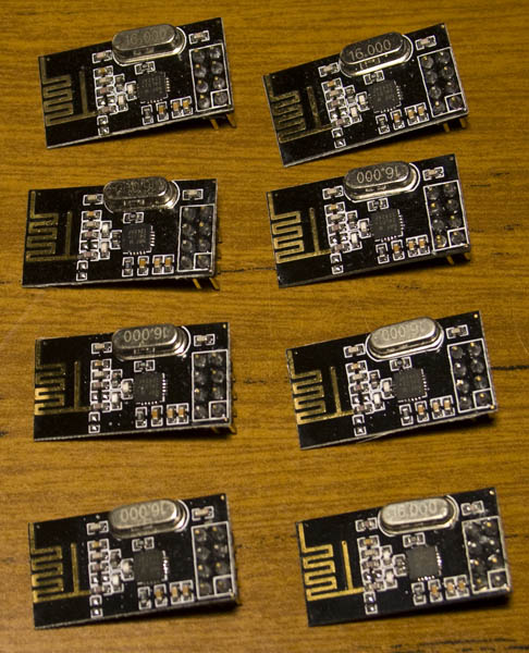
As the nRF24L01 modules are so cheap I bought quite a lot of them and have been thinking about networking them together. I have the idea of using nRF24 to be able to find out which other nRF24’s are around then then eventually be able to forward traffic for one another if it can’t communicate with a nRF24 that may be too far away but that’s an idea for later on.
The nRF24L01 allows for up to 6 receive addresses but I want to make this much higher so the way I decided to do this was through software and it would allow for up to 255 addresses. It would use all 32 bytes of data that we can send and its format is:
From address (byte 0)
To address (byte 1) – address 0 means it’s for everyone
Forward address (byte 2) – 0 means it’s a normal packet, 1-255 means to forward it to the address
Acknowledgement (byte 3) – 0 means no ack is needed, 1 means ack is needed back, 2 is the ack to send back, 3 is the ack to send back when forward is complete
A downside of the AT Mini Matrix Ctrl is that if you have your animation only playing a few times an hour that you are very likely to miss it. You could have it running every minute for a specific time but it’s not that great if no one is there to see it.
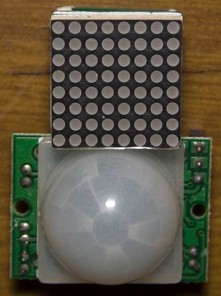
The solution to this is to use a PIR module (H8157 on Ebay) to detect if someone is around. The problem is that the PIR module is quite large compared to the led matrix so it would look out of place.
I started looking at IR transmitters/receivers and using them to reflect off a surface which would detect if someone was there however to have decent accuracy you really needed to use quite a bit of current which isn’t what I wanted. So back to square one, what can we do with the PIR module?
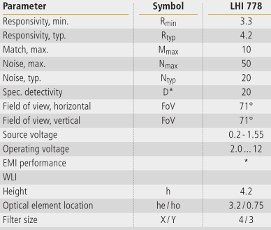
After researching the PIR sensors themselves, some datasheets (above is a random datasheet I found) said that they already had some noise reduction and some had application examples. The PIR sensors themselves can cost $2 or more even on Ebay which was odd as the PIR module was about $2 itself.
Just a small update on the AT Mini Matrix Ctrl which has now been updated to v0.4 that now allows for us to save space to store text without using animations and have the text scroll right to left. Download: AT_Mini_Matrix_Ctrl_v0.4
https://www.youtube.com/watch?v=4Qi4KpzdbCY
#define A 0
#define B 1
#define C 2
...

// Text array
prog_uchar ledLetters[26][8] PROGMEM = {
  {24,8,20,20,20,28,34,119}, // A
  {124,34,34,60,34,34,34,124}, // B
  {30,34,64,64,64,64,34,28}, // C
  ...
I’ve added a text array so we don’t have to store letters as animations.
AdvanceVGA – Play your GBA on the big screen! Swap out the LCD for our board, solder some wires, connect 5V USB and VGA and you’re ready to go.
GBxCart RW allows you to backup GB/GBC/GBA ROMs, save or restore game saves and re-write supported flash carts. Mini RW option available for GB/GBC only.
Wireless Gameboy Controller – Use your Gameboy, mGB, GBC, GBA, GBA SP, GB Micro, NDS and NDS Lite as a wireless controller on Windows, Linux, Raspberry Pi, etc, and on your NES, SNES, N64, Gamecube and Wii.