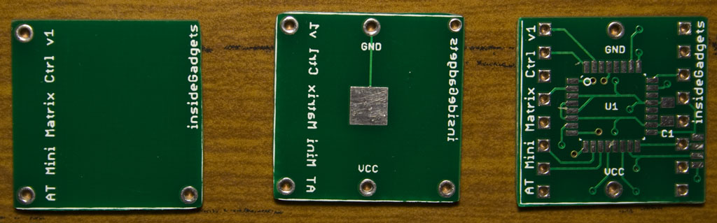
The PCBs for the AT Mini Matrix Ctrl (new name for the AT Mini LED Matrix) have arrived!
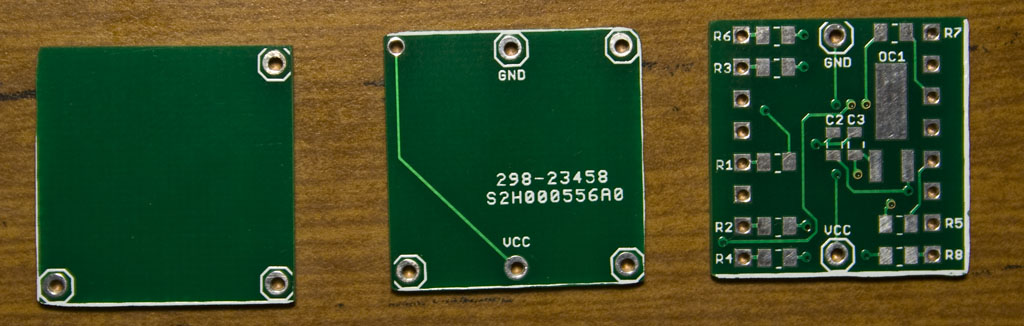
After cutting up the PCB by hand, we are ready to build it. There’s a small mistake with middle PCB’s silkscreen being the wrong way round.
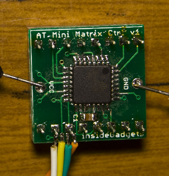
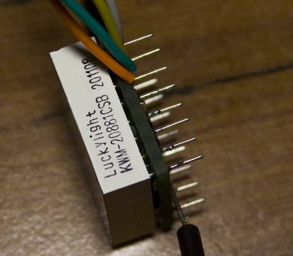
Soldered an ATmega168 with programming wires on the bottom, the 32KHz crystal, 1K SMD resistors and LED matrix on the top. There’s a small grap between the LED maxtrix and the PCB, thought it would fit right on but the 32KHz crystal must be a little too big.
When you work in IT, you see all kinds of network cables, some are labelled, some aren’t, some places I can imagine have a mess of cables so I thought how could tracing a cable be easier? I know that cable tracers exist but you have to unplug the network cable in order to trace the cable, how about making an in-line network cable tracer that you can install once and leave it there?
(sneak peak of the outcome)
My first thought was to somehow fit LEDs to existing cables and have a button which would light up the cable but this means that all network cables would need to be replaced so this isn’t suitable. So it’s time to take a look at a network cable and what we can do with it.
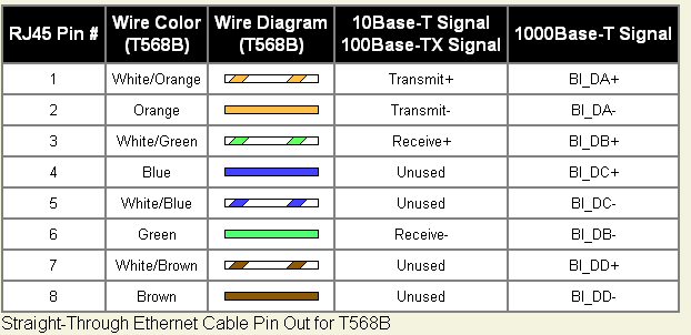
From Wikipedia, we can look at the wiring scheme where we have 2 pairs of cables used for transmitting and 2 pairs of cables for receiving.
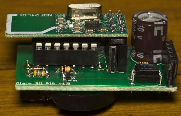
From Part 6.5, the PIR PCBs arrived and now I’ve got all the PIR sensors (except 1) on them. When I connected up these PCBs to the PIRs I found that randomly they would go off when the alarm server had them switch on. Eventually I found that the modification I made to the broken PIR had to be made to all PIRs.
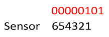
What I’m looking to do now is to see which sensors are checking in with the server which will also serve as a way to check if the 3V battery for the PIR PCB has gone flat. When the PIRs/Siren are sending their random number to check in, the last byte is 0 or 1 to say if they are a PIR or Siren.
By modifying the higher bits of the last byte to say which device it is. For example, 00000101 would mean sensor 1 has checked in.
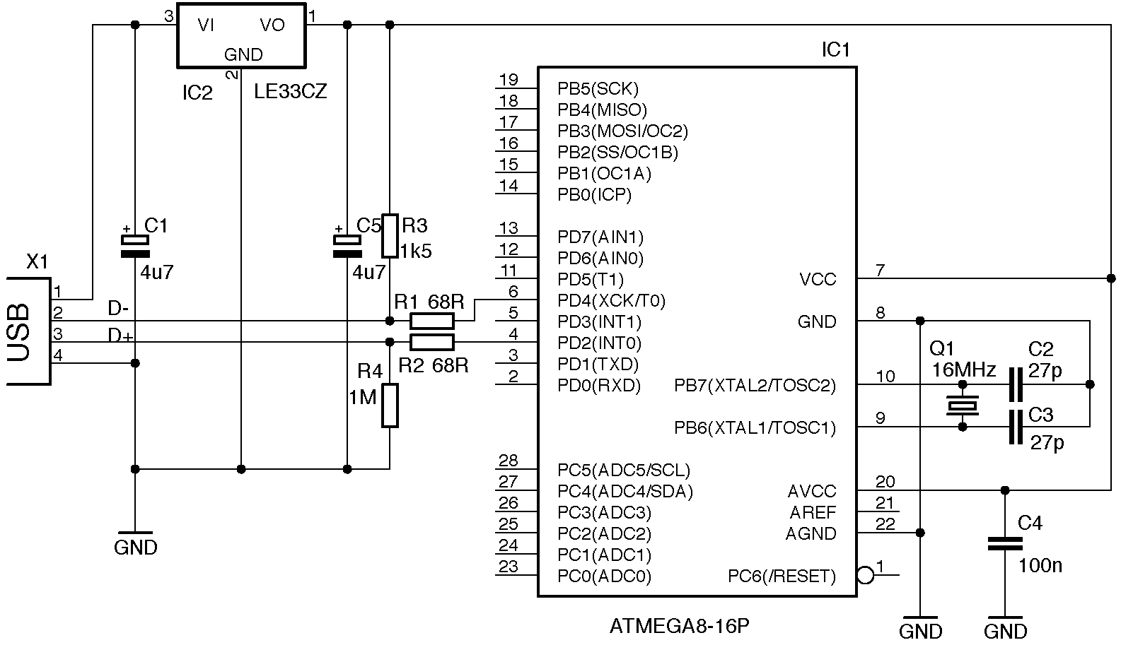
Following on from Part 1, we decided to use the ATmega48A instead of using an ATtiny with 2 shift registers and have an example animation working. In this part we’ll look at adding the 32.768KHz crystal, keeping track of the date/time and using PGM to store the LED animations.
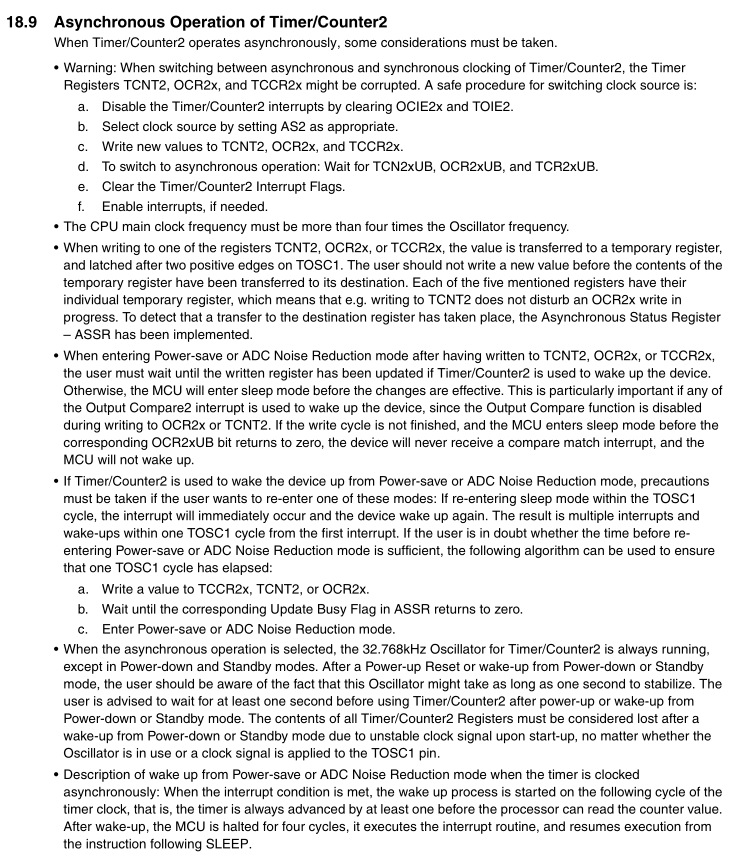
We plug in our 32.768KHz crystal to the XTAL/TOSC pins but before we start to use the crystal there is a start up sequence and other considerations which we need to follow that’s shown on the ATtiny48A datasheet.
// After a Power-up Reset or wake-up from Power-down or Standby mode, the user should be aware of the fact
// that this Oscillator might take as long as one second to stabilize
_delay_ms(1000);
sei(); // Turn on interrupts
We have our start up sequence above which I’ve made from the PDF. We select the clock source with by enabling AS2, reset all the registers and select our prescaler which I’ve chosen to give us the highest overflow of 8 seconds because exact timing isn’t that important to me and means power will be saved too – instead of waking up every second it just wakes up every 8 seconds.
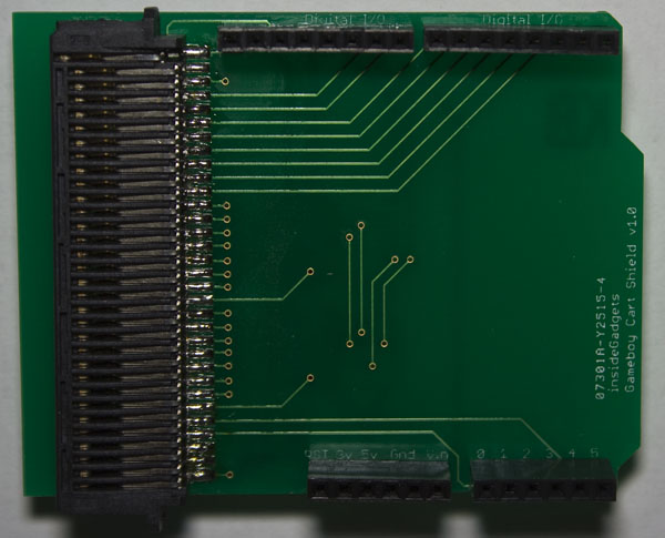
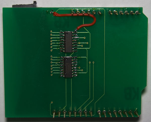
It’s been nearly 2 years since I last worked on my Gameboy Cartridge Reader (GBCartRead) and I never released a PCB but it has been something I’ve been meaning to do for a while which I can now check off my list.
I received the PCBs for the Gameboy Cart Shield a few days ago, soldered all the components and noticed that somewhere along the lines I didn’t connect up the VCCs together so I have a bodge wire on the bottom of the board. Something I should have done was make the silkscreen text much larger than what it current is.
The PIR PCBs have arrived to be used on my alarm system.
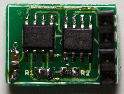
It all fits in nicely, with the nRF24L01 on top of the ATtiny and the 3V battery holder on the bottom.
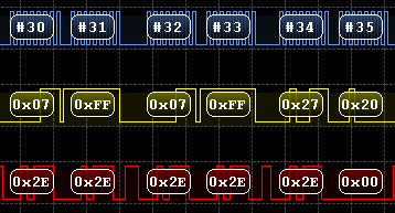
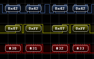
After testing 4 PIR boards at a time it seemed to work however after a few days of testing there seemed to be a board which would fail to connect. I connected up my logic analyser to a working PIR board and then to the one that wasn’t working after some time and below is the capture after it loads the random data to transmit.
Working PIR
Not working PIR
As you can see both request the status by sending 0x07 however the response is 0x2E vs 0x42 (Also notice how it sends us the reply on the same packet that we send the status request).
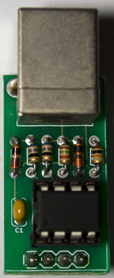
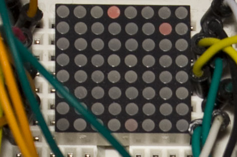
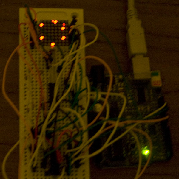
A while ago I picked up a small 20mm 8×8 LED matrix (LEDM88SMR) and have been thinking about making it battery powered to display some animations or text on specific dates such as on new years eve or on a birthday. I’m thinking of placing all the components on the underside of it so it will have more height but to not exceed the 20mmx20mm width/length.
The first thing is to build the circuit up with the Arduino using 2x 74HC595s and since I’ve worked with LED Matrix’s before, I already have some code I can reuse. Now that it works, I thought I would start designing the PCB (a bit later on it will be re-designed). Download 8x8_LED_Animation for the Arduino.
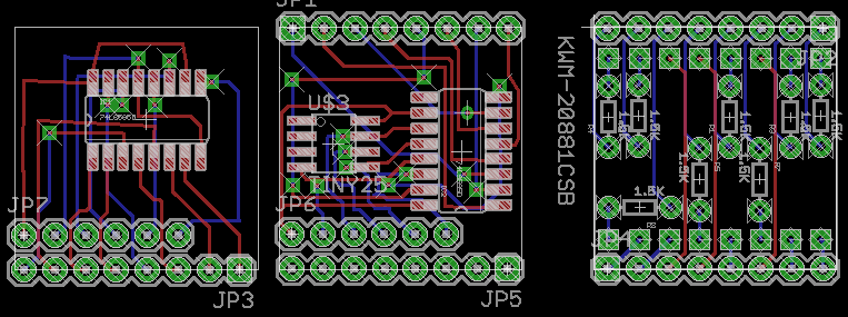
What I like to do first is lay out all the components and then draw in draft wires as place holders to make sure there won’t be any overlapping wires. I came up with 3 PCBs (left is bottom board, right is top board) which mount on each other using the Arduino style headers plus 1 more PCB for the battery. This design has an ATtiny25/45/85, 2 shift registers and 1.5K resistors.
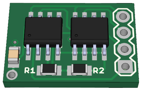
So the Standalone Temperature/Voltage Logger has worked out but I wanted to make a temperature logger more smaller and in doing so, switch back to the two board idea I originally used – one be the logger and the other be the reader.
It appears that most people who have bought the SATVL go with the 512Kbit EEPROM so we’ll provide that EEPROM as the only option and use 2 bytes per reading. In wanting to make everything smaller, it’s time for us to switch to SMD parts.
The most important part is which ATtiny MCU to go with. I was thinking of the ATtiny10, a very small chip but it only has an 8 bit ADC. The next MCU I thought of was the ATtiny13 but I found that the cost of it was more than an ATtiny25, so the ATtiny25 it is.
(sneak peek of PCB) .
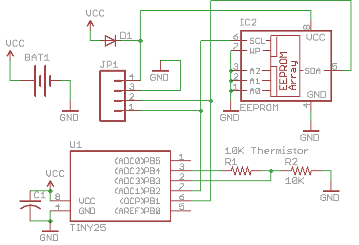
Logger Schematic
The logger board will be very simplistic, just a 10K thermistor, 10K resistor, 0.1uF capacitor, diode, battery and 4 pin header which breaks out VCC, GND, SDA and SCL. When we want to extract the data, we need to remove the battery and connect the 4 pin header to the reader which directly connects to the EEPROM. The reason the diode is there is so the ATtiny25 doesn’t power up and start re-logging.
I’ve decided to come back to this project after learning how to use the ATtiny’s ADC in differential mode. With the ATtiny44A we can use a gain of 20x for the differential mode and if we used a 1 ohm resistor with a load of 100uA, it would give us reading of 2mV (0.1mV x 20) which means we could remove the op-amp from our circuit.
I also wanted to remove all the level shifters from the circuit and have it all powered by the USB instead of using a battery. There was an example of a V-USB circuit which used a 3.3V low voltage dropout regulator and I was able to get my hands on an LP2950.
Since we will be running the ATtiny44A at 3.3V it can’t run at 16MHz but it can run at 12MHz and V-USB supports this too (if we didn’t get the ATtiny44 “A” version then 12MHz at 3.3V isn’t supported).
AdvanceVGA – Play your GBA on the big screen! Swap out the LCD for our board, solder some wires, connect 5V USB and VGA and you’re ready to go.
GBxCart RW allows you to backup GB/GBC/GBA ROMs, save or restore game saves and re-write supported flash carts. Mini RW option available for GB/GBC only.
Wireless Gameboy Controller – Use your Gameboy, mGB, GBC, GBA, GBA SP, GB Micro, NDS and NDS Lite as a wireless controller on Windows, Linux, Raspberry Pi, etc, and on your NES, SNES, N64, Gamecube and Wii.