Posted in Projects on Jan 5th, 2013
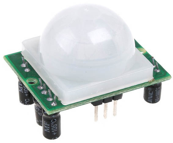
I’ve decided that I’ll use the PIR sensor I bought from Ebay for $2 as a front door detector to detect anyone approaching the front door, sometimes people don’t ring the doorbell and knock instead (hard to hear sometimes) or a courier drops off a package at the front door. The idea is to have a small box powered by a battery to send the signal via Wifi to a receiver which can have an LED/Buzzer.
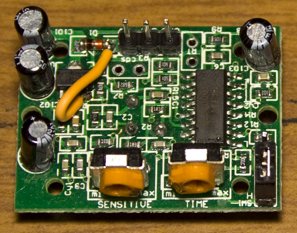
The PIR has an input voltage of 4.5 to 20V, has adjustable pots for sensitivity and time and has an output that goes high when the PIR detects something, it also has the BISS0001 chip that’s present on the Alarm PIR sensor which I have.

Current consumption at idle when at 9V is about 60uA which isn’t bad but I’d rather not use a 9V battery due to the size. I checked the output of the regulator which was 3.3 volts so I decided to wire the regulator’s output to the pin VCC input so it would bypass the regulator.
(more…)
Read Full Post »
Posted in Projects on Dec 24th, 2012
A few months ago I bought myself a really cheap camera so I could record the front of my car whilst driving (dash cam), it cost $6 off Ebay. I’ve seen lots of dash cam videos and thought I’d join in too as there have been those kind of moments where you just wish you had a camera. Instead of manually turning the camera on, off and then pressing record I wanted to automate this with an MCU.

The camera has two buttons – one to switch it on and off and the other button to record or take a picture. It has a microSD card slot and USB connector which you can use to grab your pictures/videos and charge the built in Li-Poly battery.

One other thing to mention is that I’ve found if the battery goes flat when you are recording it destroys the microSD card – you can still read from it but can’t write to it any more – maybe I just have a bad batch? Above are all the microSD cards which suffered this fate. A downside with this camera is that it records everything in MJPEG which means your microSD card will be used quickly – a 27 minute recording was 2.4GB but what can you expect for the cheap price.
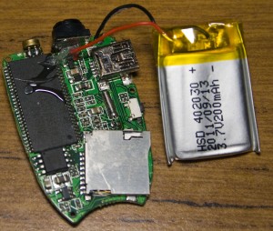
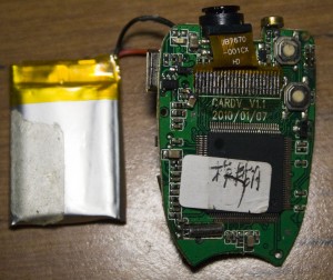
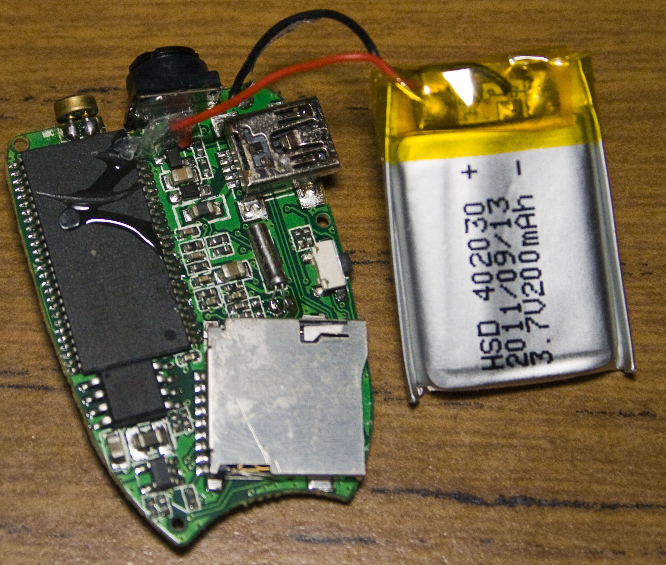
Two screws later and we’re in. We can see the Li-Poly capacity is 200mAh, we have a memory chip to the left and the processor chip to the right. I found that when the camera was turned on or recording, it draws 105-120mA and when the Li-Poly battery is charging the charger supplies it with about 100mA and slowly starts dropping current.
(more…)
Read Full Post »
Posted in Projects on Dec 18th, 2012
Following on from Part 5, we looked at using optocouplers to turn on the PIR’s reset until the PIR settled down otherwise it trigger the alarm. In this part we’ll add on the code to save the 256bit random number to the EEPROM when the power is disconnected, reduce the NRF24L01 power consumption when we are sleeping and look at the PCB made for the PIR.
Detect battery removal
The reason we need to save the 256bit random number to the EEPROM is so when we power on the PIR again, the random number doesn’t start from the initial random number we programmed. We need to add a capacitor of sufficient size to keep the ATtiny84 running for a few milliseconds to save data to the EEPROM. After some testing I found that a 1000uF capacitor was more than sufficient for this task.
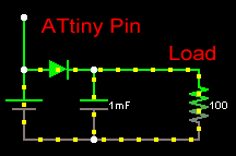
The easiest way I could think of detecting whether the 3V battery was removed was to use a sckotty diode from the 3V battery going to the capacitor, have a wire connected to the 3V battery to the one of the ATtiny’s pins. The ATtiny and NRF24L01 run from 2.6-7V after the voltage drop, both will run just fine.
(more…)
Read Full Post »
Posted in Projects on Nov 10th, 2012
Following on from Part 4, we looked at adding the sirens, SMS sender and the modifications needed to the server. In this part we’ll look at modifying the PIR sensor so we can add on the wireless client to turn it on and off.

This should be simple enough to do, just add a mosfet on the switch of the PIR and that should be it. However one thing I didn’t take account of was when you turn on the PIR, it transmits it’s signal to the alarm system like it was triggered which is a big problem.

We need to go back to the BISS0001 datasheet to see what we can do. Firstly I tried to pull 2Out low before powering up the PIR but it made no effect.

After looking at the datasheet more there is a Trigger disable input (pin 9) which is enabled if the voltage is more than the supply voltage (Vdd) * 0.2. On the board I found a 1M resistor connecting the supply voltage to pin 9.
(more…)
Read Full Post »
Posted in Projects on Nov 3rd, 2012
Following on from Part 3, we looked at securing the communication between the PIRs and the alarm system. This part was going to be on PIR and the extra steps I ran into when adding the PIR client to it but we’ll leave it for next time. In this part we’ll look at the adding the sirens, SMS sender and the modifications needed to the server.
We’ve upgraded to the ATtiny84 so we can use an extra pin or two, below is how we are utilising each MCU.

Adding on the sirens

Originally my plan was to have the sirens listening for when the server would contact them – it worked but it was a bit complex when it didn’t need to be.
(more…)
Read Full Post »
Posted in Projects on Oct 11th, 2012
The Standalone Temperature/Voltage Logger has now been updated to v1.2 – download here and is now back in stock with the v1.1 PCB now available which fixes the Q3 Mosfet issue with the v1.0 PCBs.

The v1.2 update fixes a bug where the calibrateOscillator function wasn’t been called when USB was plugged in so only a few ATtiny’s would work. Also instead of using delay whilst waiting for the ADC result we now use the ADC noise reduction sleep mode which should give just that tiny bit more accuracy and also saves a little bit of power.
Read Full Post »
Posted in Projects on Sep 29th, 2012
Following on from Part 2, we looked at two way communication between the PIRs and the alarm system. In this part we’ll look at how we can secure the communication otherwise potential attackers could listen to the messages and control our PIRs. This part might be a little over the top for your typical project (e.g a logging project) but for my alarm system I think it’s worth going into.

Finding a solution
As anyone who knows a little bit about security, designing your own security protocol is a bad idea which I knew from the start but still wanted to give it a try. One problem we have is that the server only has 2 alarm states to send to the client, either turn on or turn off.
(more…)
Read Full Post »
Posted in Projects on Sep 20th, 2012
Following on from Part 1, we defined the modifications to make to the existing alarm system. In this part we’ll look into the two way communication for the PIR sensors, to be able to turn them on/off wirelessly.
We learned how to use the nRF24L01 module in one way communicate mode so we’ll need to modify that to have two way communication so that the PIR sensor can check in with the alarm system and receive a response back. I have 5 PIR sensors which I’m looking to do this for so the alarm system will need to listen for each one. From here on in I’ll refer to the PIR as the client and the alarm system as the server.

By looking at the datasheet it shows a configuration with one receiver communicating with 6 other transmitters at once. The nRF24L01 has 6 data pipes and when ever a packet arrives, we can check which data pipe it came from. This is useful because we may be in the middle of talking to PIR1 when PIR2 sends a packet, we wouldn’t know it was PIR2 if we don’t check the data pipe. If this happened, we would want to ignore PIR2’s packet and have it retry again later but in my example we only do one receive and one transmit so it doesn’t matter in my case.
(more…)
Read Full Post »
Posted in Projects on Sep 8th, 2012


I picked up a cheap alarm system from Ebay (the “99zone” alarm) which came with a few wireless IR sensors and magnetic sensors that run off batteries and it all seems to work well and I’m looking to add more functionality to it.

The IR sensors have a switch to turn them on or off and are powered by a 9V battery. The only problem is that this switch is more of an inconvenience as you have to walk around to each sensor to turn them on or off. You could leave them always on but eventually the battery will run out in maybe a few weeks/months – the batteries were supplied with the alarm system so they might be pretty cheap batteries. When the IR is activated, it draws about 8mA for 2 seconds.
(more…)
Read Full Post »
Posted in Projects on Sep 2nd, 2012
I received the PCBs for my ATtiny Programmer Adapter v1.1.

Built it up and it works well, I’m happy with it. The ISP connector is a tight fit, if I made the 6 pin / 10 pin ISP connectors any closer the connector wouldn’t fit. Tested all slots except the ATtiny48/88 slot as I don’t have one of those MCUs.

Should have probably added an LED to show there is power to the board. Need to buy some machine pins to make it easier to insert/remove the chips.
Read Full Post »