GBCartRead the Arduino based Gameboy Cart Reader project is now completed. I’ve done everything I set out in terms of saving and restoring my Gameboy saves :). GBCartRead has been updated to version 1.3 which has all the features of reading the ROM, reading RAM and writing to RAM.
The video above shows all features being used.
Now I just need to think about what my next project will be… the logical thing would be do the same with the SNES or I was thinking of working more on the gameboy by emulating a gameboy cartridge with the Arduino 😉
So what good is reading the RAM if we can’t write back to it? This is what we’ll cover in Part 3: Write to RAM.
Writing to the RAM is quite similar to reading the RAM except instead of reading the data pins you write to them. This part won’t be as large as our previous parts because we’re really just re-using our Reading the RAM code. Let’s jump right to the code.
I hope you’ve gotten a feel of how we can access the Gameboy Cartridge in Part 1 and now it’s time for the real part that I was looking forward to: Reading the RAM of the cartridge. Before we start I recommend you read Part 1: Reading the ROM.
In this tutorial I’ll still be using my F1RACE game that uses MBC2 which is actually simpler compared to others because some of the other MBC’s use RAM banking; which is just like ROM banking as you should already know if you read Part 1. I’ll also cover another MBC to show how RAM banking works.
When we want to access the SRAM for reading or writing we firstly have to enable the SRAM, this is done by setting RD/WR and sending a specific command to the MBC. The command is called “initialise MBC” which is found on the VBG website and is given to us as 0x0A, this translates to data pins D1 & D3 should be on (00001010). The other thing to take note of is that RD needs to be set to 1 (off) and WR to be set to 0 (on) when we give the 0x0A command.
Recently I’ve been collecting retro gaming consoles such as the Gameboy and SNES and whilst playing a game on the SNES I actually lost all my saves when I turned it off (turns out the battery got disconnected from the cartridge). The thought came to me, how can I backup the save game from these devices? There are cart readers around but they seem to be harder to find in this day and age so I thought why not make one myself using the Arduino as it’s so versatile!
Before I begin looking into extracting the save games I’ll look into dumping the ROM which was a way for me to learn how to communicate with the Gameboy cartridge. I’ll now guide you in how to communicate with the Gameboy cartridge to read the ROM so without further delay, let’s begin!
Gameboy Cartridge
Let’s firstly take a look inside a Gameboy cartridge. A typical Gameboy cartridge contains:
ROM is where the game’s data is stored
SRAM is where your save games/high scores are keep. Some cartridges (like the one of the left) don’t have this chip because they don’t store any data or it’s built into the MBC
MBC is the memory bank controller, it allows us switch ROM banks to read the game’s data from the ROM.
MM1134 IC to control when SRAM should be run from battery or not
Just a quick post to let you all know that the Standalone Temperature Logger has now been updated to v1.1. This update is for the re-design of the PCB board, it’s now been adjusted so that there are components close to the battery solder joints thus making it easier to solder the battery.
Welcome to Part 9, we have our schematic from Part 7 as below now it’s just time to design and build our PCB. Not a whole lot of content for this post, mostly just pictures.
First thing I did was position the ATtiny85 near the center of the board and position the resistors as close to each other as possible. After that it was just a matter of finding where everything else fit. To make the board as small as possible I decided that I would mount the battery on the back of the board.
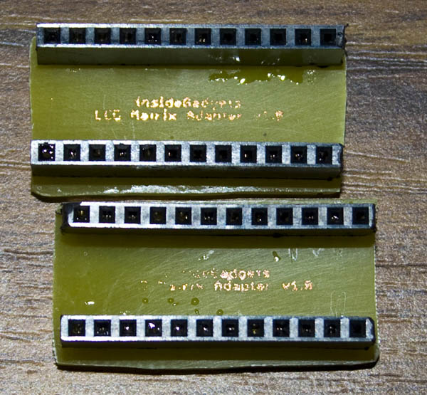
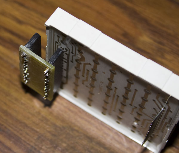
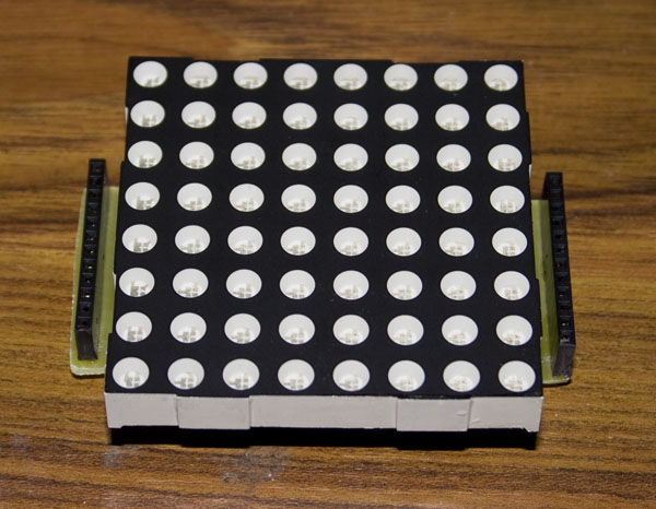
I’ve just made a very simple LED Matrix Adapter for the 60mm LED Matrix so that you don’t need to use the breadboard any more. The PCB is just a few wires with headers, really nothing special.
Welcome to Part 8, before we get starting with making the PCB I thought I’d review my code/hardware plus add some more functionality to our project.
We don’t need a Watchdog f_wdt variable
On review of my code and the example watchdog code I used, I found that the watchdog f_wdt variable wasn’t adding any value to our code. I came to this conclusion because when you run the system_sleep() function and it reaches sleep_mode(); it sleeps there. When the Watchdog timer wakes it up, it heads to the watchdog vector (ISR(WDT_vect)) and now since it’s awake again it continues to run next bit of code.
// This will work because we are initialising the watchdog vector and
// once the watchdog times out, it will wake up, go here,
// do nothing and continue our code
ISR(WDT_vect) {
}
Now I’ve give you an example of where we might need the f_wdt variable.
Welcome back! In this part we’ll explore how we can reduce our power consumption which will allow us to move from 2 AA batteries to a 3V coin cell.
When the whole circuit is operating in logging data mode and at 2.68 volts, it’s taking up 1.06mA. First off this 1mA is much lower than our assumed 2-3mA because we are running at 3V instead of 5V, less voltage means less power consumption. Using the Battery Life Calculator with a 240mAh battery it gives us a estimated battery life of 8 days. Lets see how low we can get our power consumption to!
Welcome to Part 6, it’s been a long project so far and we are coming close to the end. In this part we’ll explain how and why we need to change our circuit and code from 5V to run at least at 1.8V.
The reason being because of communication between the Arduino and ATtiny, if you were to run the ATtiny at 1.8V and hook up the Arduino to it, the ATtiny Digital or Analog input can only go to a maximum of 1.8V. So you’re feeding 5V from the Arduino to the ATtiny at 1.8V, you’ll overload the inputs and are highly likely to damage the chip.
How can we connect both microcontrollers together if they operate at different voltages?
Option 1: If you recall from Part 4 we learned about voltage dividers, we can use this technique to divide the voltage in such a way that the Arduino’s 5V output can be divided to lower voltage. We can use a 39K resistor along with our already 10K resistor
AdvanceVGA – Play your GBA on the big screen! Swap out the LCD for our board, solder some wires, connect 5V USB and VGA and you’re ready to go.
GBxCart RW allows you to backup GB/GBC/GBA ROMs, save or restore game saves and re-write supported flash carts. Mini RW option available for GB/GBC only.
Wireless Gameboy Controller – Use your Gameboy, mGB, GBC, GBA, GBA SP, GB Micro, NDS and NDS Lite as a wireless controller on Windows, Linux, Raspberry Pi, etc, and on your NES, SNES, N64, Gamecube and Wii.