Feed on
Posts
Comments

Category Archive for 'Projects'

I thought it might be interesting to go over the noteworthy software/hardware changes since the initial release of GBxCart RW, some of them include changing the MCU, using TinySafeBoot as the boot loader so the firmware can be easily upgraded, some GB flash cart support and various fixes.

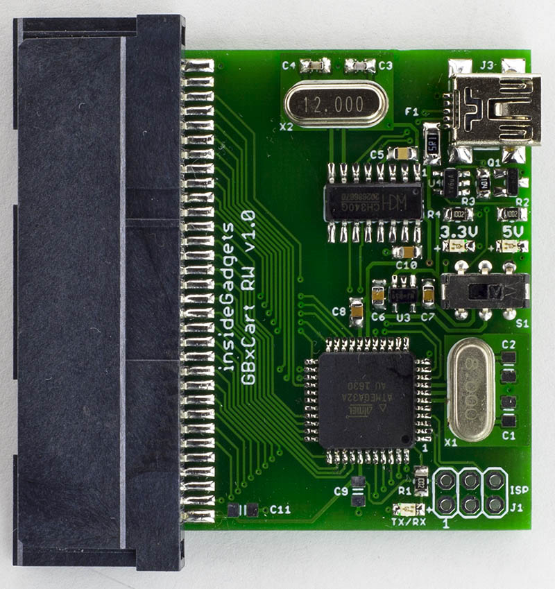
Change to ATmega8515L
In the initial release I was using the ATmega32A which was just short on 2 pins for displaying the 3.3V/5V LEDs so I ended up using an inverter to do that. I didn’t really want to keep using an extra part (inverter and supporting parts), plus it wouldn’t be able to support GB flash carts in the future as I didn’t have enough pins for the GB cart audio pin as that’s how you program some of them. I did a more broader search and came to the ATmega8515L which gave me 3 more I/O, just enough for the audio pin and 2 LEDs so I could remove the inverter (it also seems like the MCU some other GB cart devices use too).

Gameboy Camera SRAM misread bytes
One user reported that their GB camera SRAM dumps weren’t consistent, I could replicate the issue and it looked like some of my photos had some vertical lines, some more visible than others. It seems that when reading the SRAM, we have to delay an extra MCU cycle, so it went from 1 nop to 2 nops, shouldn’t be too noticeable, now those lines are gone and the SRAM files are always identical.

Additional EEPROM checks / Fix for GBA 32MB carts
There seemed to be an 4Kbit EEPROM which allowed 64Kbit reads without repeating the same 8 bytes over and over again, if it did repeat, that was the way we would know if it was a 4Kbit EEPROM. So I added another check which read the first 512 bytes and then second 512 bytes which wouldn’t be possible for a 4Kbit EEPROM so it should repeat the same 512 bytes which it did.

Before I was addressing the EEPROM at 0xFFFFFF but it seems like this didn’t work with 32MB carts. I re-read the GBATek information page and I must have missed the part where they briefly mention 32MB carts, in the end I changed it to read at 0xFFFF00 and it worked fine.

Flash save writing, not waiting for sector erase / Forgetting to end write before switching banks / Stuck in Flash ID mode
One user reported that their Pokemon save games weren’t being written correctly. When writing to the flash I was erasing the next sector, waiting 25ms as per some datasheets and then I wrote to that sector. I read somewhere that as flash gets worn out, it takes longer to do the sector erase so instead of waiting for 25ms, I’m now waiting to read back 0xFF from the first byte of that sector which resolved the issue. Later on I bought Pokemon Ruby and I could tell that doing a sector erase on it took longer than 25ms.

(more…)

Read Full Post »

With the LiPo battery fires I hear from time to time, I thought it might be a good idea to build a temperature monitor when charging LiPo batteries. Ideally you would put a little case over the battery with the temperature sensor inside (a low cost thermistor would do) and then if the temperature rises by approximately 15C from when you switch it on then it should alarm you.

Whether the batteries get noticeably hot when they are about to pop is something I will need to test one day (I’m sure they would to some degree) but if they do pop, I have heard that pieces can potentially go everywhere so it’s best to contain the batteries when charging.

(sneak peak)

I decided to go with an ATtiny24A which would have enough pins for 6 thermistors, a buzzer, a shift register to control the LEDs and it will be powered by a LiFe 14500 battery.

Once the battery is inserted, it should read all thermistors to check if they are connected, get the base line temperature and then begin to monitor the connected thermistors. If no thermistors are connected at the start, any thermistor that was connected becomes disconnected or the temperature rises by about 15C, it should indicate which one it was and turn the buzzer on.

(more…)

Read Full Post »

From the last part, we looked at the client/server interaction, server communication with the ESP8266, used an EEPROM to keep an event log/sensor names and added a RTC. Today we’ll add a simpple admin page to set things like the RTC, sensor names/types, email addresses for which we’ll also have the ESP8266 send us email alerts plus have a look at a PIR interference issue, various other small improvements/fixes and a quick look at PCBs and 3D printed case; a lot to cover!

The PCBs arrived a few days after I posted the last part so I built them up and tested them, it all seemed to work apart from the door sensor, 2 traces were touching each other (my mistake) so I just cut the track and re-wired it.

The Zippy 700mAh LiFe battery I was originally planning to go with went out of stock so I went looking for other LiFe options, turns out there is a 600mAh 14500 size which just fits a AA battery holder. If I had of re-done the PCB I could have made it a bit bigger to fit the AA holder on the back. Pricing wise, it costs a bit more ($10 for 2) but for the form factor that it offers I think I’ll stick with it.

For the 3D printed case, I made something as small as possible that would fit the PCB, PIR sensor and a slot for the antenna that pokes out. I ended up putting the LiFe battery on the back of the PCB anyway with a cutout that fits it. If you look at it front on, it doesn’t look too bad, but from the side, it does look a bit bulky but it’ll do. The LED is on the bottom left of the PCB, kind of hard to see with the case on; you could use transparent material but I didn’t have any, so I made a little hole and inserted a plastic light pipe which does the trick. Later on I think I’ll paint the cases.

(more…)

Read Full Post »

From the last part, we looked at how to use the Atmel ATSHA204A device for random numbers / HMAC with a private key so that the client could verify what the server sends and vice versa. Today we’ll test the client/server interaction, have the server talk to the ESP8266, add an EEPROM to keep an event log/sensor names, RTC plus I’ll briefly touch on FHSS for the Si4432.

For the client, we can stick with the ATtiny84 (or ATtiny841 which I have a few spare) and for the server I’ve gone with an ATmega168, both the client and server have an ATSHA204A device with the same private key as each other. In terms of security, it’s not the best if physical access is obtained, a client could be taken away and still have access to the system and act as a server, the best thing to do in that case would be to re-key the private key.

Client side

// Generate random number
atsha204a_command_random_number(DELAY_WDT);

// Check in
RH_RF22_resetFifos();
RH_RF22_txHeaderRequestType = CHECK_IN;
RH_RF22_send(randomNumber, 32); // Send 32 byte random number ([0] will be changed by the server)
RH_RF22_clearInterrupts(); // Must be cleared here as it goes low before the packet is sent
RH_RF22_wait_for_transmit();
RH_RF22_sleep();

// Wait for server to do nonce and HMAC
watchdog_sleep(T128MS);
watchdog_sleep(T32MS);
watchdog_sleep(T16MS);

// Wait for packet to match our address
if (wait_for_valid_packet()) {

After combining the ATSHA and Si4432 code, we can have a look at the client check in. We run the random number command function for which I’ve added the option of using _delay_ms or the watchdog timer for low power consumption. We do the usual clearing of FIFOs and interrupts, set the request type as check in and send the random number to the server.

Strangely enough if you clear the interrupts before you load the packet and turn the transmit mode on, the Si4432 will set the interrupt low straight away so it will seem like an interrupt occurred before the packet was even sent. Turns out you have to set it right after you turn the transmit mode on and it works fine. Edit: This is because we need to reset Register 06h. Interrupt Enable 2 to 0, default is 0x03 (Enable Chip Ready and Enable POR)

I’m now using Si4432 interrupts when receiving or sending a packet which allows the ATtiny to sleep during that time and wake up on a pin change however we don’t want to keep the Si4432 listening for too long. After some trial and error I found that using the watchdog to sleep for 128ms + 32ms + 16ms gives us just the right delay for the server to generate the HMAC and for us go into receive mode when its close to sending us the HMAC. I measured that it takes about 9ms after the packet is loaded for the packet to be sent (i.e enpksent is 1).

(more…)

Read Full Post »

From the last part, we looked at using the Si4432 module for communication between the sensors and server with the ESP8266 Wifi module as our web server. Today we’ll look at the Atmel CryptoAuthentication ATSHA204A device which will let us use truly random numbers and use the HMAC function with a private key (stored securely on the device) which means no hashing libraries will be required for the ATtiny.

The way I intend to use the device is for it to return a 32 byte random number which we can change 1 byte of so the server and client can communicate with that 1 byte, feed it into the device which will generate a HMAC from that random number and a private key.

There are plenty of other use cases described in this Atmel PDFs:
Atmel-8794-CryptoAuth-ATSHA204-Product-Uses-Application-Note
Atmel Crypto Products REAL.EASY Training Manual 2Q2015 r6

I’m using the I2C version which should be quicker to access and easier to use than the the 1 wire version, should save us a little bit of battery life too. Before we hook it up to the ATtiny, we need to test it so we’ll be using the Arduino, there are one wire library examples out there but none for the I2C version. Atmel also has some libraries available for the CryptoAuthentication product suite however there was a lot of functions and jumping around so the only code I used from that library was the CRC function.

The device contains 3 zones:
– 16 data slots where you can load a 256bit key to each slot
– Configuration zone includes allows you to set how the data slot keys can be used, whether the keys can be read/written, a counter to provided limited use of the data slot keys, the unique serial number and programmable I2C address to name a few.
– One time programmable (OTP) zone contains 64 bytes that can be used as read only memory.

The configuration zone and data slots/OTP can be locked to block any writes to them, this is useful if you don’t want keys re-programmed and disallow how each data slot can be used. In order to write to the data slots, the configuration zone needs to be locked.

(more…)

Read Full Post »

Mini Temp Logger v1.0 Released

The Mini Temp Logger v1.0 has now been released and is available for purchase.

This project has quite a few SMD parts, soldering them by hand can take a long time so I decided to give stencils a go as I hadn’t used them before. I ordered one from OSHStencils for the top side, it came within 1-2 weeks which was good. I played around with how to align the stencil, applying the solder paste, etc, after a few tries I got relatively good coverage of the pads, placed the components, soldered them with the hot-air rework station and it worked out nicely.

We also have a GUI now which automatically picks up the device so you can easily connect/disconnect them without closing and re-opening the program.

I built a few more of them up with two different RTC capacitors, 7pF and 8pF, both of them seemed to worked well and the 8pF one almost didn’t need any digital trimming. I popped them in the freezer but both of them eventually stopped working after a few hours so that’s no good so it’s back to the 6pF caps.

A quick comparison between 2 loggers (top) and 3 loggers (bottom – in freezer, something isn’t right with our freezer, pretty hot day when the test was run) placed right next to each other shows that temperatures between them were very close to each other so the TMP102 temperature sensor is pretty accurate.

Read Full Post »

From the last part, we decided on our design – use a DC-DC to pre-regulate the voltage feeding into the LM350 linear regulator that’s controlled by a PNP transistor and we’ll use a N mosfet with op-amp for the current limiting. Now we’ll add in everything else – the displays, ADC, DAC and Digital pot, it’s taken a while to reach this point.

I started checking for the parts and came up with the following:

16bit MCP3425 I2c ADC ($3.1)

It has an on-board 2.048V  ±0.05% voltage reference which is pretty nice. It does 15 samples per second at 16 bit, a bit low but it’ll work.

12bit MCP4726 I2c DAC ($1.4 x 2)

I like this DAC because you can either use VCC or any voltage from 0.01V as the reference voltage which can be buffered (could use resistor dividers to set voltage) or unbuffered. This is going to be very handy for setting the current which passes through the 0.1 ohm resistor. We will need 2x of this DAC, you can purchase different address options (can be harder to source).

(more…)

Read Full Post »

GBxCart RW v1.0 Released

GBxCart RW v1.0 has now been released and is available for purchase (I decided to rename it from GBxCartRead as we also do writing too). The PCBs arrived and everything worked however I got the switch connections reversed, so changing it to the left means 5V is selected and to the right means 3.3V is selected, so just be extra careful when using a GBA cartridge.

// Set pin output as low
else if (receivedChar == SET_OUTPUT_LOW) {
	char portChar = USART_Receive();			
	usart_read_chars();
	uint8_t setValue = strtol(receivedBuffer, NULL, 16);
	
	PORTD |= (1<<LED);
	if (portChar == 'A') {
		PORTA &= ~(setValue);
	}

I’ve decided to add raw I/O access to the Gameboy Slot pins through the COM port as some users may not be able to update the ATmega with new versions, so if there were any carts I would like to add support for, we could control the all pins from the software, it’ll be slower but it will work.

(more…)

Read Full Post »

A little while ago I picked up a low cost 3D printer, the Malyan M150 and after printing all sorts of things from Thingiverse, I decided to move over to designing cases for my projects which was the original intent for the purchase.


         (old alarm clock – 16 x 11 x 5cm)                        (new alarm clock – 6 x 4 x 3cm)

I still use a nightstand alarm clock as a backup just in case I don’t wake up from my phone alarm however the current alarm clock that I’ve had for years is a bit too bright at night so I end up having to cover it up or move it so I’ve decided that I might build my own which would allow me to turn off the display or dim it significantly by pressing the snooze button.


(video showing functionality)

The clock will be minimalistic, it will have 4 buttons: snooze/display off/on, alarm on/off/set alarm time while held down, hour and minute, LEDs for alarm on & PM indicator and just have a little buzzer as the alarm which we’ll PWM to a suitable tone of our choosing. We’ll use a medium sized 4 digit 8 segment LED display that I had bought from Ebay some time ago (ZTT-5461BS, common anode), the MCP7940M RTC and an ATmega48 which I had lying around which will have just enough I/O pins for our needs. I’m able to re-use some code from the LED clock project and I’ll also try out the RTC alarm functions.

(more…)

Read Full Post »

From the last part, I talked about some of the ideas I had for the Alarm system v3, two of which we’ll look at today, using the Si4432 module and the ESP8266 Wifi module.

The Si4432 module is has an adjustable frequency range of 240MHz to 930MHz so you could use any frequency you wanted but to keep it legal I’ll use a frequency between 433.075 to 434.775MHz. The input voltage is 1.8V to 3.6V, you have the option to adjust your transmit power from 1dBm to 20dBm (17mA to 85mA), we have RSSI available and have TX and RX FIFO buffer of 64 bytes. An interesting feature is that you can disable the FIFO and access the RX/TX of the chip in direct mode in real time, something that could be useful for streaming applications. We can also have interrupts on RX received and TX transmission complete.

I bought a couple off Ebay, used the RadioHead RF22 library and hooked up the TX and RX to 2 Arduinos and it worked well, the default frequency is 434MHz. Range wise I didn’t have any problems in the garage or outside.

I started increasing the output power and once I reached anything higher than 8dB, the receive text became corrupted, adding a 100uF capacitor on the TX helped and then I added a 10uF capacitor on the module itself to reach 17dB but it occasionally still resulted in corrupted text, I think I’ll still to 8dB or less.

(more…)

Read Full Post »

« Newer Posts - Older Posts »