Posted in Projects on Jan 22nd, 2017
From the last part, we switched to the CH340G USB to serial converter which gave our read speeds a bit of a boost, we looked at reading the GBA ROM, SRAM reading/writing and how to automatically determine ROM/SRAM sizes. In this part, we’ll cover EEPROM read/write, Flash writing and determining EEPROM size and checking if we have SRAM or Flash.
I was previously looking at the ATmega32A which I’ve received and was able to switch to, it has just enough pins, with 2 pins to spare, one will be an LED pin and the other will detect the 5V/3.3V switch so we know whether we’ll be interfacing with the GB or GBA.
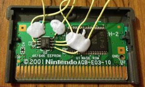
On to the EEPROM, I found the GBATek page which gives a explanation on how to address the EEPROM and what to do when reading/writing so it’s a good and simple resource to use though I wanted to see for myself how the GBA interfaced with EEPROM with any timings I need to consider. I broke out the logic analyser on the Fila Decathlon game which uses a 4Kbit EEPROM.
Writing to EEPROM
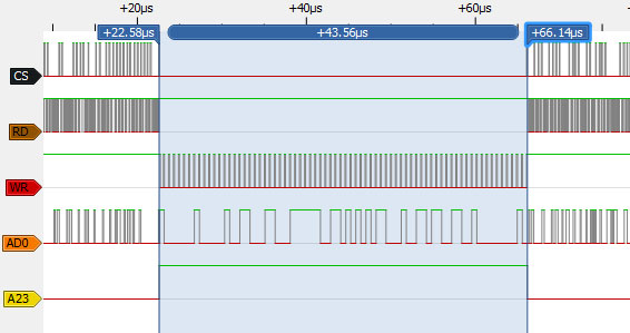
Thankfully the game allows you to save to the EEPROM after the first event so I was on my way. For a write, we can see that CS goes low, RD goes high, WR is the clock line as we drive the EEPROM serially, AD0 is the data and A23 goes high. If we were to read from the EEPROM, the RD pin would be the clock and the WR pin would be high.
(more…)
Read Full Post »
Posted in Projects on Jan 7th, 2017
From our last part we received our PCBs, did some RTC crystal testing, some of the results that I couldn’t explain was that it drifted a few seconds some days whilst my home clock that used the same RTC didn’t. After a lot more testing (weeks, ouch!), it turns out that my computer was the cause, its clock changes by a few seconds every few hours, even though I had it syncing up in the mornings, so I switched to using an online time website. After a bit of calibration, I left it running for 10 days and it’s only 1 second slower so I’m happy with that result.
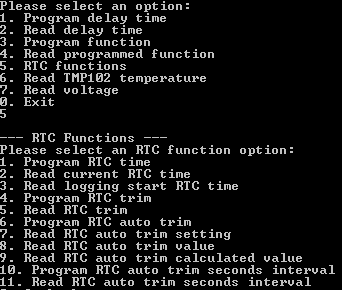
I was previously thinking about adding in a RTC auto trim function to trim based on temperature which I thought might help to resolve the initial issue I had but it wouldn’t have actually done much (due to my timing issue), in the end I implemented it and it will work when it’s logging or not plus now the RTC related functions in the interface program have a dedicated section. As per the crystal PDF specs, they had a formula for this purpose: -0.035 x ((T – To) x (T – To)). We can program in the interval (seconds, minutes, hours or days) for the auto trim function to run, whether we want it on or off and a few options to read back the PPM trim value calculated and how it would affect the current static RTC trim.
(more…)
Read Full Post »
Posted in Projects on Dec 25th, 2016
From the last part, we looked at the design for the new GBxCartRead project which will read the Gameboy & Gameboy Advance ROM/RAM. For the data transfer between the PC and ATmega I went with the V-USB ATtiny85 method (for testing the communication method incase the USB to serial chip didn’t work) and was able to re-use some of the GBCartRead code to successfully read Gameboy cartridges though it was quite slow.
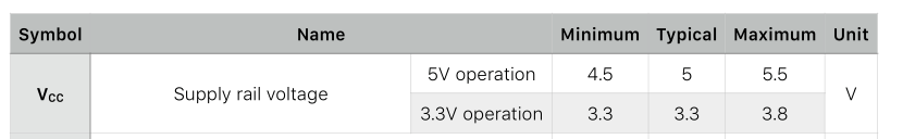
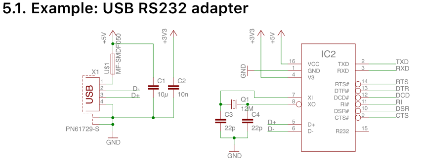
The faster method for data transfer is using a USB to serial converter chip like the CH340G, it will mean less parts overall and should result in a faster speed, if it works. The CH340G looks simple enough to control and hook up, it can be powered by 5V or 3.3V which is good for us as we’ll have to switch between the GB and GBA. It needs a 12MHz crystal, a few capacitors, a polyfuse (if you want), the USB+/- lines and the TX/RX lines, the other lines we can ignore.
I hooked it all up without the crystal capacitors (I usually do this with AVR chips and they work fine) but it didn’t work, only when I touched the crystal pins would it work, add in the 22pF capacitors and it works fine. I performed a quick loopback test at 1Mbps and that also passed. Now we just need to change a bit of our ATmega / PC code to work with it, I’ll be using the Teuniz RS-232 library like I did in GBCartRead. After a quick test, reading 128KB of ROM now only takes 4 seconds!
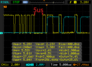
One thing we do need to be careful of is if the PC sends 64 bytes of data at once, the CH340G will dump all this data to the ATmega as quickly as possible, there is about 5uS of dead space where the ATmega can do something else (if you are curious the blue trace shows when the ATmega receives a USART packet and falls once the SRAM write is performed). Instead of doing the write command after each byte received when writing like I was doing, I will read all 64 bytes on the ATmega, perform the task and then send an acknowledge byte back.
(more…)
Read Full Post »
Posted in Projects on Dec 6th, 2016
It’s been 5 years since I started making GBCartRead (GB Cart Shield) using the Arduino to read Gameboy ROMs and save games. GB Cart Slots at the time of this post are becoming harder to find (Aliexpress are selling used ones) plus I have some time on my hands so I think it’s time to re-do it without the need of the Arduino. There have been a few users ask if GB Cart Shield supported the Gameboy Advance which it doesn’t, so I will look into supporting that for this new project which I might call – GBxCartRead (the x shows it supports GB/GBC/GBA).
I’d like to remove the shift registers that the GB Cart Shield currently has and look for an AVR MCU which has enough pins to cover the GB slot pins at a reasonable cost. There are few options like the ATmega162, 165, 169.

I choose the ATmega169A for $6 as it came with free shipping from RS and I will be using it for another project, it’s pretty big. It has 54 I/O lines, way more than what we need though it will allow us to use 3 complete PORTs dedicated to the GB I/O.

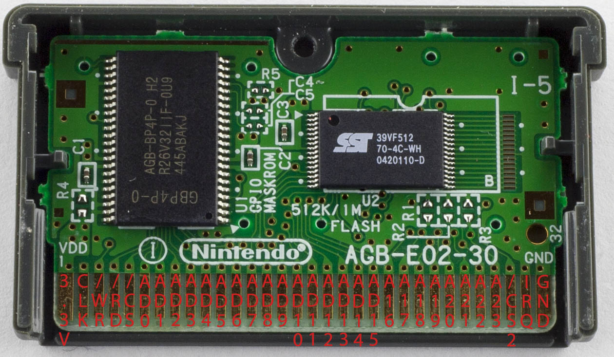
GBA cartridges are similar to GB carts except that they require 3.3V, use 3.3V logic, have 24 address lines and they switch the first 16 address lines into data lines when reading the ROM. As per the GB carts, you pulse WR low to write, RD low to read and CS low whilst doing either. They have a CS2 line which is dedicated to the SRAM, pulse CS2 low to access it. An upside over GB carts is that we don’t have to do any bank switching for reading the ROM due to the 24 bit address line (32Mbit max) but a downside is that the GBA cart header doesn’t contain any useful information about ROM size, RAM size, etc. There is however a useful gba.xml file from the MAME project (\mame\hash in the source) in which they have documented which cartridges contain what chips.
(more…)
Read Full Post »
Posted in Projects on Dec 1st, 2016
A while back I made a Small Programmable Power Supply which at first was going to have a P mosfet to control the voltage but I switched to a LM2596 DC-DC when I found the mosfet was getting too hot. The power supply has worked well for me over the past few years but now it’s time to build something better. One of the problems with the old power supply was that when you got to the higher end of the voltage range (6V+), there were big jumps in voltage (0.2V-0.5V) when you turned the knob higher, this is because of the digital pot and resistor divider used to adjust the voltage.
At first I was thinking of doing a 3 output power supply, each output would have their own dedicated DC-DC however upon testing the Richtek DC-DC that I’ve used before with the digital pot, I would still run into the same problem. What we could do is stick a linear regulator after the DC-DC and give it 2-3 volts headroom which would save us from having the linear regulator drop all the voltage on it’s own. I’m currently testing the LM350 which is similar to the LM317 but can handle at least 3 amps and allows for voltages of 1.2V to 33V, I’ll be looking at powering this supply from a 19V power adapter so I could have a voltage range of 1.2V to 15V or so.
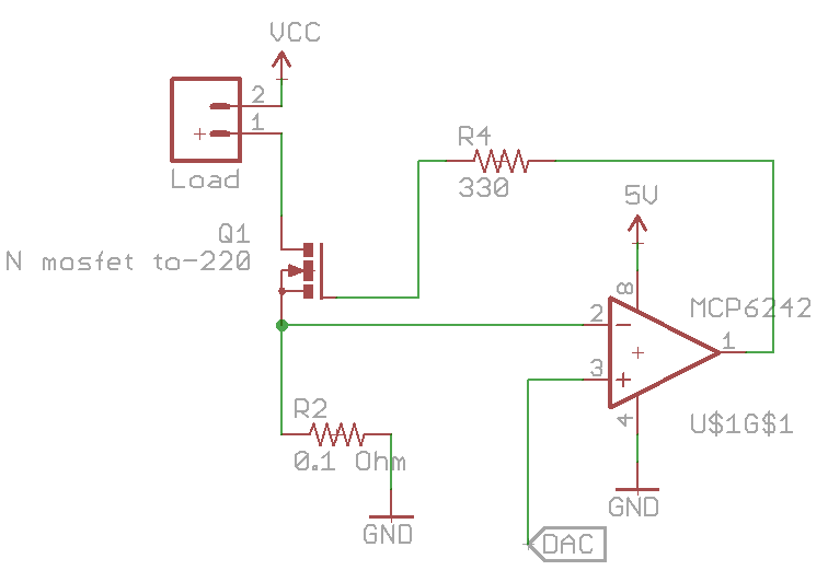
I would also like to add current limiting to the power supply and to see how much current is being drawn by the device under test, I’m looking at either 2 or 3 amps. We can re-use the constant current dummy load circuit and by placing the load before mosfet, the op-amp will regulate how much current will flow through the mosfet. One problem I’ve found is when you hit the current limit, the mosfet is in the linear region just like in the dummy load so it gets really hot. I thought I could get away with a small mosfet without a heatsink but I was wrong, I’ll have to go with a TO-220 style with a decent heatsink. On the other hand, if you did want go with a small mosfet, you could detect that a current limit occurred and then turn off the output.
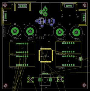
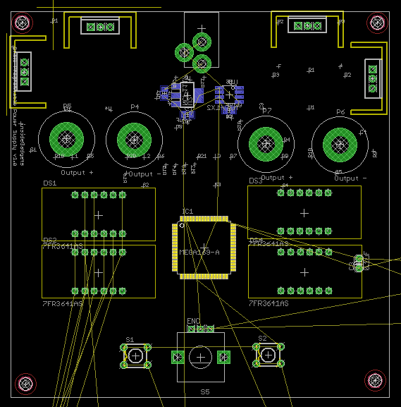
Above is a rough look at what it could look like (10x10cm). I’m looking at having 2x of 4 digit LED displays, one for voltage and one for current, the same rotary encoder like last time and having the power supply be dual output. Two push buttons on either side of the encoder would select the the voltage and then another push for current, the LED display has a little dot light at the bottom right so this could be used to indicate which display was being set or I could add 2 LEDs on either side of the display. No need for shift registers any more as I’d be using an ATmega169A which has enough pins to drive the displays directly.
(more…)
Read Full Post »
Posted in Projects on Nov 4th, 2016
Its been a while since I last worked on this officially project though I have done a little here and there to gather ideas and testing for the new design. To briefly recap, my first alarm system was on I bought from Ebay and made some modifications to it then I made my own alarm system that has PIR/Door sensors with the NRF24 wifi module.
Since my last post on the alarm system, I’ve now removed the 433MHz remote and switched to the Raspberry Pi so I can switch the alarm on/off via Wifi which makes things easy. Also I’ve moved to the SIM900A for SMS sending. It’s been almost 2 years now, I’ve had to charge up of the PIR modules batteries once and most of the door sensors have stopped working properly either because of the coin cell didn’t last, the NRF module or its position so I gave up on them and I’ve had 2 false alarms, one I think the battery was running too low (my voltage cut off may not have been high enough) and not sure about the other one.
Some of my ideas for the new project are:
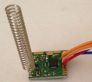
Use the 433MHz Si4432 module for the wireless network
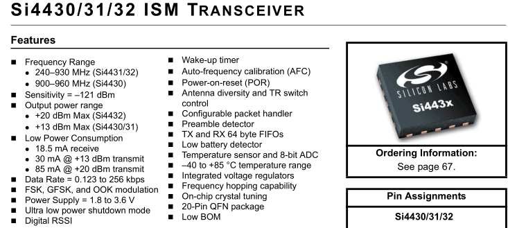
Using this module over the nRF 2.4GHz should allow for better reception in areas that reception was hit and miss, this was in the garage and some spots around the house. Input voltage is 1.8V to 3.6V so it’s quite low. Current consumption is 1uA when sleeping, 18mA in receive and you can change your transmit power from 1dBm to 20dBm (17mA to 85mA), so I might go for 5 or 8dBm which might be around 20mA. The downside is that it’s a lower frequency it will need to be receiving and transmitting for a longer period of time.
Price is $3 for the module from Ebay so that’s pretty cheap.
(more…)
Read Full Post »
Posted in Projects on Sep 11th, 2016
From our last part we added the RTC including programming the time from the PC, some fixes, estimated battery life and briefly looking at some logging results.
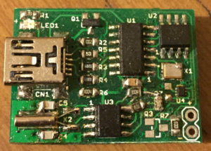

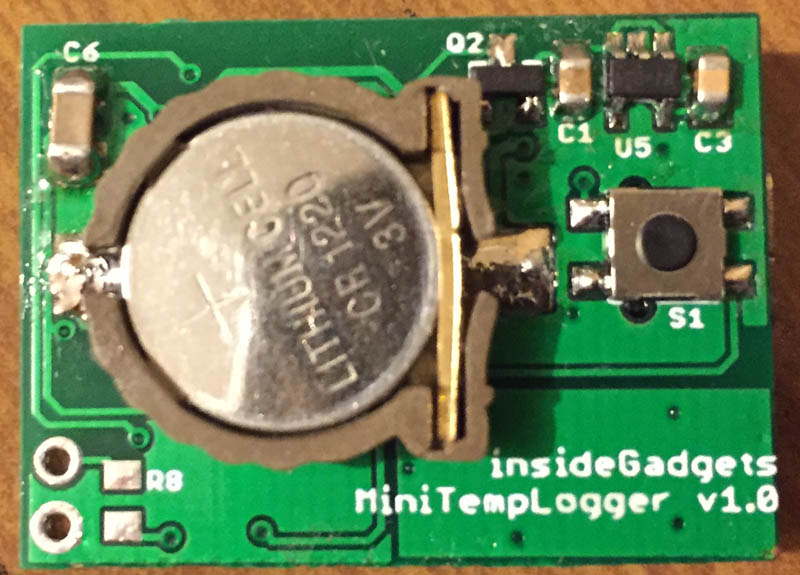
I made a quick couple of changes to the PCB and squeezed the voltage logging back in to just have that option available again, briefly tested the new SOT23-5 LDO without issues. A few weeks later and the PCBs turn up, everything looked good and then I built it and found out I forgot to add the I2C resistors and RTC MFP resistor too! A couple of cuts to the board to reveal the tracks and I could solder the resistors and it works.
I started testing the RTC with different capacitors to see how accurate it can be, it seems to work good for a few hours but eventually it started to drift by a couple of seconds after a day which could be due to temperature changes (15C to 25C) over 24 hours or possibly the PCB design. I have a small single sided RTC PCB for my big clock and that used to be 1-2 seconds drift every month which I’ve had for almost a year though now it’s drifting by 3-4 seconds after a few days too, so it is starting to sound like it could be temperature problem thought it doesn’t seem to be as bad; I have had one day where it didn’t drift and then the next day when it did by a lot.
(more…)
Read Full Post »
Posted in Projects on Jun 3rd, 2016
From our last part we looked at adding in the TMP102 sensor, experimenting with I2C pull-ups, re-testing the voltage switcher diode and other improvements/fixes. This time we’ll look at adding in the RTC including programming the time from the PC, more bug fixes, estimating battery life and briefly looking at some logging results.
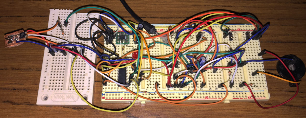
I started off re-designing the RTC crystal layout which I would also make into a little board to connect up to the breadboard and since I already have a RTC clock project I can use that for reference.
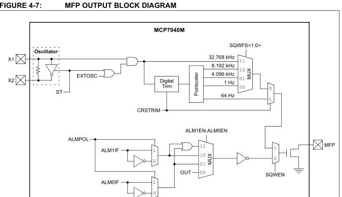
The MCP7940M has the option to output a 1 Hz square wave which is what we’ll use to wake up the ATtiny every second. We no longer need to use the watchdog timer which takes about 4uA when in use where as the RTC takes 1.2uA.
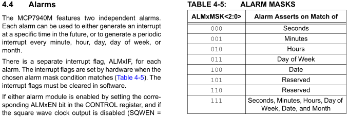
An alternative is to use the alarm capability build into the RTC to wake us up however this would mean that for 1 second logging, you would need to constantly reconfigure the alarm for the next second which could be complicated in the end and you might spend even more current reconfiguring it however for longer logging delays say every minute or hour it would make sense but I’ve opted to keep everything simple for the moment and just use the 1Hz output.
(more…)
Read Full Post »
Posted in Projects on Apr 3rd, 2016
I’ve had the HobbyKing Rattler for some time now and I’ve been making small modifications here and there which have accumulated over time and has gotten to the point where it would be nice to have everything on a custom PCB.
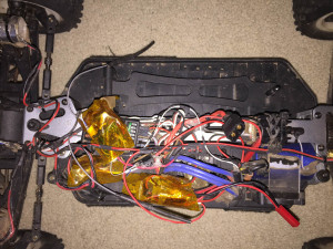

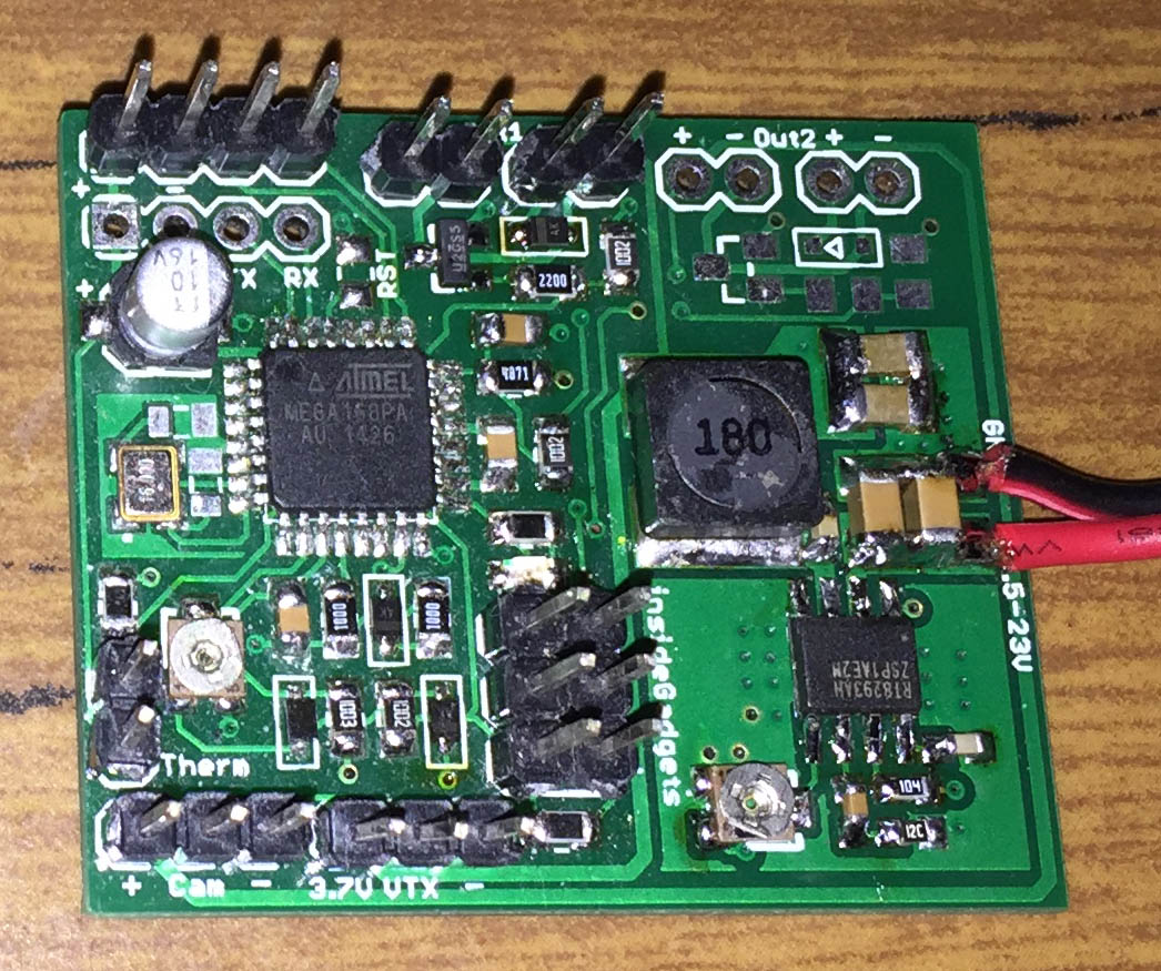
Here’s how everything looks at the moment, pretty messy with kapton tape wrapped around each separate board, we have a large DC-DC converter bought off Ebay a while back for the video transmitter (VTX), an ATtiny control board for the lights/connecting to the receiver and an ATmega with another board doing the temperature/video osd. On the right, we have the finialised PCB.
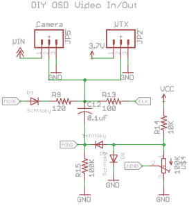
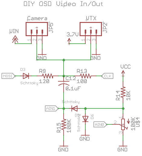
Let’s start off with the video OSD as it’s what the whole board revolves around, I’m using DIY OSD which uses an ATmega with some resistors, diodes and capacitors to overlay text over the screen and it works fairly well. It’s written in Arduino so I’m going to have to use that and I took out the GPS code references so we can fit it into an ATmega168. There are other solutions like Minimosd use a dedicated chip (MAX7456) to do the overlay and the text it generates is better however I wanted to keep things simple and small.
(more…)
Read Full Post »
Posted in Projects on Mar 12th, 2016
From our last part we looked at choosing capacitors for our LDO, testing our I2C timing, switching to a 1Mbit EEPROM and using EEPROM page writes. This time we’ll look at adding in the TMP102 sensor, experimenting with I2C pull-ups, re-testing the voltage switcher diode and other little improvements.
It has been a good while since I’ve worked on this project, though it’s not all bad, it does give me a chance to re-look at the project and pick up on things I might have missed.
Adding the TMP102
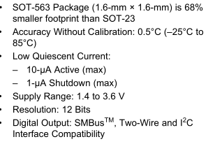

The TMP102 is a very small I2C temperature sensor with 0.5C accuracy (typical, -25C to 85C), 12 bit resolution, 1.4 to 3.6V supply and low current at 1uA shutdown and 10uA active plus it’s much smaller than what I thought so I had to use enamel wire to connect to it.
#define TMP102_TEMP_REG 0x00
#define TMP102_CONFIG_REG 0x01
#define TMP102_CONFIG_SD_MODE 0x01
#define TMP102_CONFIG_EM 0x10
#define TMP102_CONFIG_ONESHOT 0x80
...
if (!soft_i2c_master_start((deviceAddr<<1) | I2C_WRITE)) return false;
if (!soft_i2c_master_write(TMP102_CONFIG_REG)) return false;
if (!soft_i2c_master_write(TMP102_CONFIG_SD_MODE)) return false;
if (!soft_i2c_master_write(TMP102_CONFIG_EM)) return false;
soft_i2c_master_stop();
By default the TMP102 operates in a continuous conversion mode where it samples the temperature and puts it in a register at power on, we should disable this feature by enabling shutdown mode (SD).
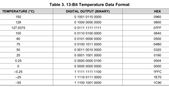
We change from 12bit data mode which lets us measure -55 to 128C to 13bit mode which does -55 to 150C by setting the extended mode bit and write the above changes by referencing the configuration register (0x01) first.
(more…)
Read Full Post »