The current doorbell we’re using at home is a bit old now and it can play up from time to time (it’s one where you rotate some screws to give a certain combination to link up with the transmitter). A majority of my time for the last few months have been with RC and now I’ve got some spare parts we can put to good use.
https://www.youtube.com/watch?v=r7_RbnRNwxY
My idea is to use a nRF24L01+ with an ATtiny for the transmitter and receiver, an old small video camera bought off Ebay, a 10mW 5.8GHz video transmitter, 5.8GHz receiver, 4.3″ monitor and some batteries. I have some more ideas for the next iteration of this project found at the end.
Doorbell Transmitter
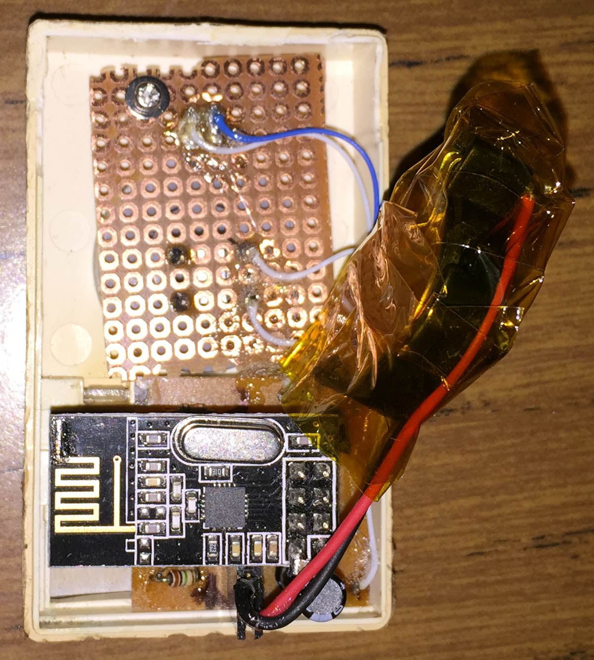
So the first part is the transmitter, I could make an acrylic box with the CNC but it wouldn’t look quite as good as a proper enclosure (though I could stack the layers), a 3D printer would be perfect for this job but since I don’t have one I decided to re-use the enclosure. I took out all the electronics and lined up a button and LED on a veroboard and it fit in nicely.
From our last part we looked at the new design for a small temperature logger project with a drafted PCB, the redesigned the voltage switching circuit and USB connect/disconnect feature and updating the data transfer function. In this part, we’ll look the capacitors for our LDO (part of the voltage switching circuit), testing our I2C timing to maximise battery life, switching to a 1Mbit EEPROM and using EEPROM page writes.
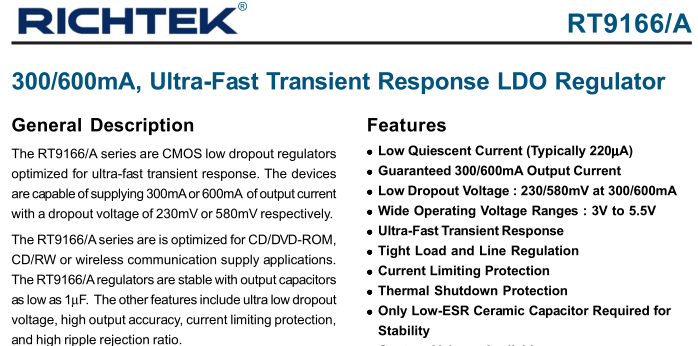
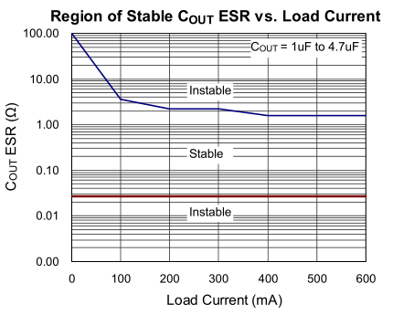
Usually when I chose capacitors for a voltage regulator, I’ve never really look at the ESR performance of the capacitor before; I assume most capacitors would be good enough for general loads, most of times they are but I thought it would be a good idea to actually test the ESR this time. The 3.3V LDO I went with was the Richtek RT9166 which is low cost and I’ve use other products of theirs (DC-DC) before so it should be a safe choice.
The input capacitance is 1uF minimum without any ESR requirements and output capacitance is also 1uF minimum (X7R) and we’re given a region of stability depending on the load – 0.3 to say 20 ohms for the small amount of current which I’ll need. I purchased one of the many ESR LCR Meter kits available from Ebay and decided to test a few caps, unfortunately it didn’t measure the ESR of some small caps properly (under 1uF) but it works on larger caps.
As part of the Mini Temp Logger design I need to look at a better way of keeping time other than using the watchdog timer as it’s fairly inaccurate. I stumbled across the Microchip MCP7940M Real-time clock controllable by I2C, you can set alarms, a clock output (likely what I might use for my project), ability to trim the oscillator in 1PPM increments (129PPM -/+ range), low power consumption at 1.2uA and the price was $1.
Choosing capacitors
This RTC recommends the use of 6-9 pF 32.768KHz crystals, the most common/cheap ones are 12.5pF and it still does work with them but it won’t be as accurate as the 6-9pF ones (and for me it sometimes stopped working), it took me a while to realise this as I was reading the preliminary datasheet for a while.
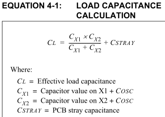
The first thing we need to do is calculate the capacitors we’ll require for our crystal, there is a standard formula which we follow for this, Cstray is usually between 2-5pF so lets assume ours will be half way at 3.5pF. I went with a low cost (at the time) EuroQuartz MH32768L crystal that has a CL of 6pF. The best match for our formula is 6pF for CX1 and CX2: (6 pF * 6 pF)/(6 pF + 6 pF) + 3.5 pF = 6.5pF which is close to our CL of 6 but you may have to vary the capacitors depending on your testing.
Interfacing
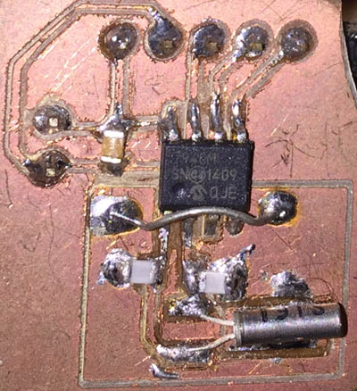
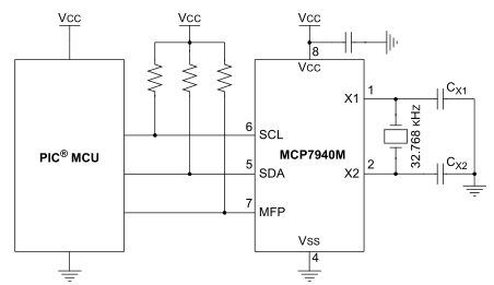
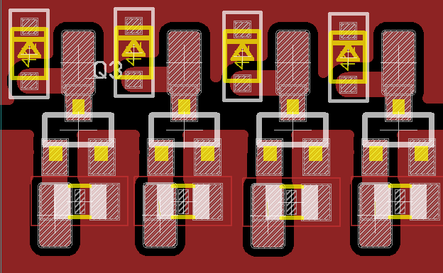
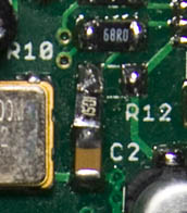
I built a simple PCB for the RTC (doesn’t look the best as I built it about 6 months ago when I didn’t use to sand the PCB) but there isn’t much to it. We just need a crystal with 2 caps, a cap for the chip and then just I2C resistor pull ups. Let’s interface with it, I’ll start off using the Arduino and we’ll move to an ATmega328 later on.
I recently got into the quadcopter hobby and purchased a UDI U818A mini quadcopter from Ebay which is fun to fly and have been experimenting changing the battery packs and adding FPV. I’ve been thinking about going to a larger quadcopter but before I do, I’d like to plan around with making my own micro quadcopter and experimenting with the software.
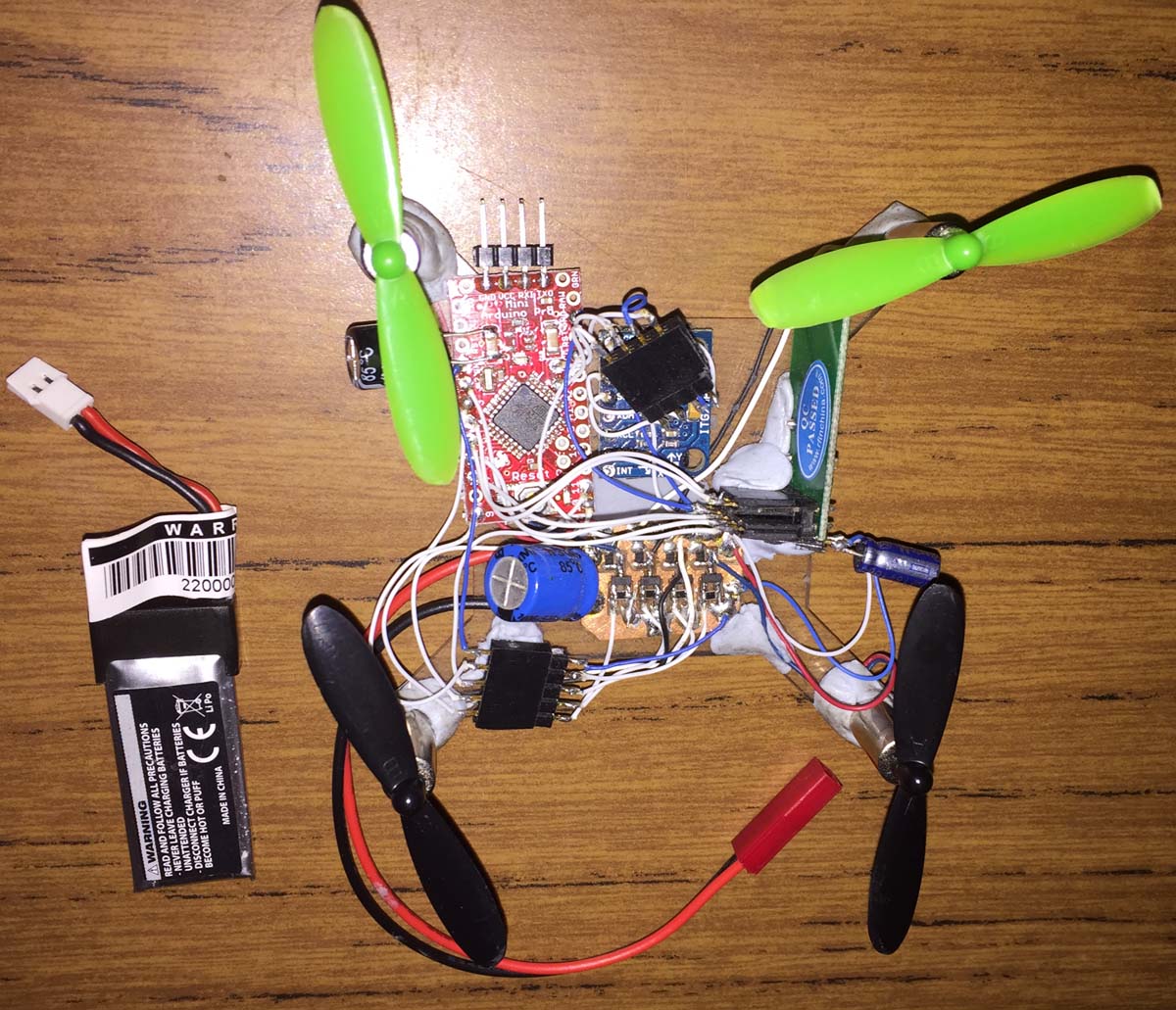
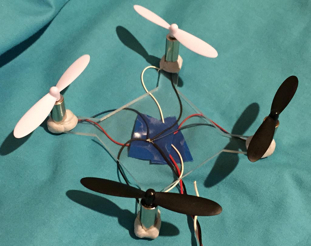
The first part was to build a frame, using my CNC I built one from acrylic just big enough to fit all 4 motors with propellers without touching each other, a bit of blu-tac later and they are semi-secured in place, good enough for testing. One big downside is that acrylic is heavy compared to most other materials.
Testing the 4 motors all at once at different voltages gave me the following current draw results – 1.7v @ 780ma, 2.5v @ 1.2A, 3v @ 1.5A, 3.5v @ 1.9A, 4v @ 2.2A but I expect that it could be double or triple that due to the wires I was using so each one might draw 1-1.5 amps each.
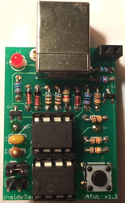
It’s been a few years since I’ve updated the hardware/software for Standalone Temperature/Voltage Logger but my recent Mini Temp Logger (MTL) project has made me think about improvements that I could also put back into the SATVL so there’s just a few quick things worth mentioning for the v1.3 update.
There has been a small hardware change, the 2 diodes have been removed which now allows for up to ~28V input voltage logging and the automatic voltage switcher has also been updated like I designed in the MTL, the PCB’s size was reduced slightly too. The reason for the 2 diodes was to protect against high input voltages because I believed that if we exceeded the 1.1V ADC reference voltage that the ATtiny would be damaged.
However after careful reading of the datasheet it turns out that all that would happen is it would read close to max value of 1023 so all is good.
A while ago I bought ten 8×8 LED matrix from Ebay for about $7 and was thinking what I could do with them. Initially I was going to hook them up in a 3×3 arrangement but thought I could a better use if I connected them all together in a row to display text and potentially I could make this all wireless. Also I could use this to display the time as 10 LED matrices are just enough to fit the time, e.g, 12:34:00PM.
I milled out a quick board to mount the LED matrix, 595 shift register, connected it to an ATtiny84 and got it to a working point. It wasn’t really worth my time to mill out 9 more so a few weeks later the PCBs arrive and I start putting everything together.
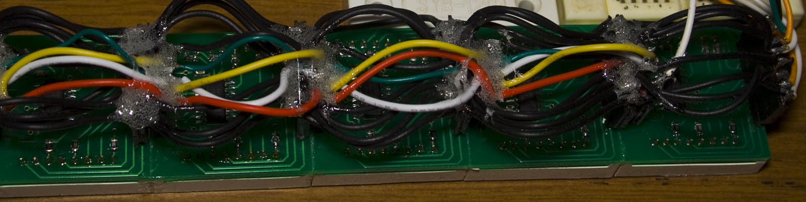
On the PCB there were some headers which would connect each matrix to each other but what I didn’t realise is that connecting the boards together was a very long process as I had to individually wire each header to each other, a few hours later and it’s done. If I were to re-do this project I would have laid out the PCBs better so they could just connect to each other without wires.
I’ve been looking to upgrade the way that I have been sending SMS’s which is through a Nokia phone using F-Bus and came across the SIM900A module. If you can spare the cash, I would recommend it over Nokia F-bus as it’s easier to use.
It’s a relatively cheap module for $20 on Ebay but you need to check that the SIM900A works in your country before buying it. By using AT commands, we can send and receive SMS quite easily and I was going to cover this but there are already tutorials around that cover it quite well.
So instead I’ll be explaining how we can use the SIM900A’s GPRS to fetch a file from a webpage and print it out so we can process the data. Potentially you could use this instead of waiting to receive an SMS, for greater data transfer rates vs price per SMS or better yet for control of a device such as a remote control car/quadcopter as long as you have mobile reception.
SIM900A Hardware
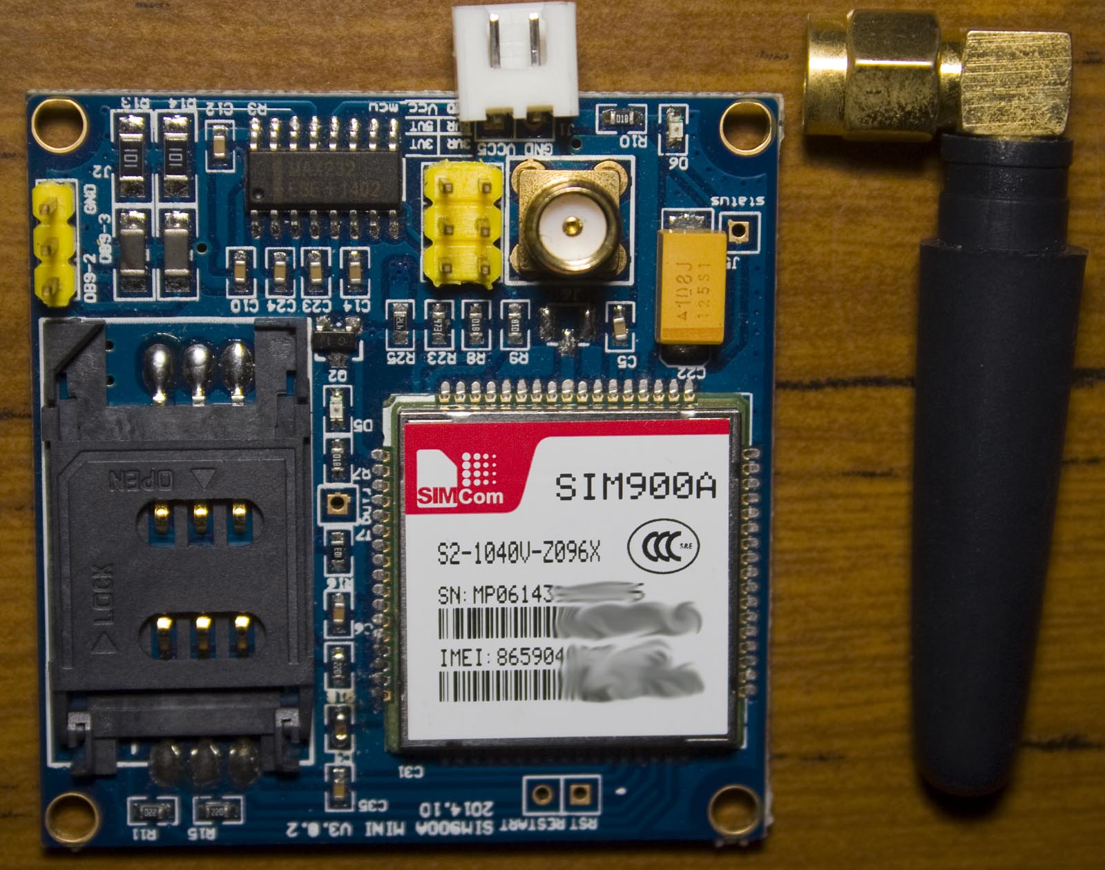
The one I bought is the “SIM900A Mini V3.0.2, 2014.10” which comes with an external antenna. The PCB has a MAX232 on board if you wish to hook it up to your computer directly.
I’ve been playing around with the idea of rebuilding the temperature loggers I’ve done in the past (SATVL / A25TTL); both have their advantages and disadvantages. I’m looking at going a little bit larger than the A25TTL so it would have a proper SMD battery holder, combine the logger and reader into one again like the SATVL and look at having an option to use the TMP102 temperature sensor (0.5C accuracy), upgrading the EEPROM to 1Mbit and possibly look into adding a RTC later on.
Recombining the logger and reader into one means the ATtiny13/25 that I’m using won’t do the job so an ATtiny44/84 or ATtiny841 should have enough pins however if we do go with the TMP102 its supply voltage is 1.4 to 3.6V which means we’ll need to use an 3.3V LDO or similar when connecting up to the USB. With 3.3V to the MCU we’re limited to a 12 MHz which is just enough to run V-USB.
I did a quick mock up of how the PCB could look like (29×15.5mm). To keep the PCB as small as possible, I’ll be using all SMD parts and going with a SOT23 LDO (Richtek RT9166) and a small 12MHz crystal (3.2 x 2.5mm). The MCU will still be using the watchdog timer (for the time being) when it’s doing the delay time so the accuracy is still going to be around 10% -/+. I’ll have the battery holder on the back like the SATVL does and the TMP102 (which is smaller than I expected) on the bottom right without the ground plane near it to reduce any effect it might have on the temperature reading.
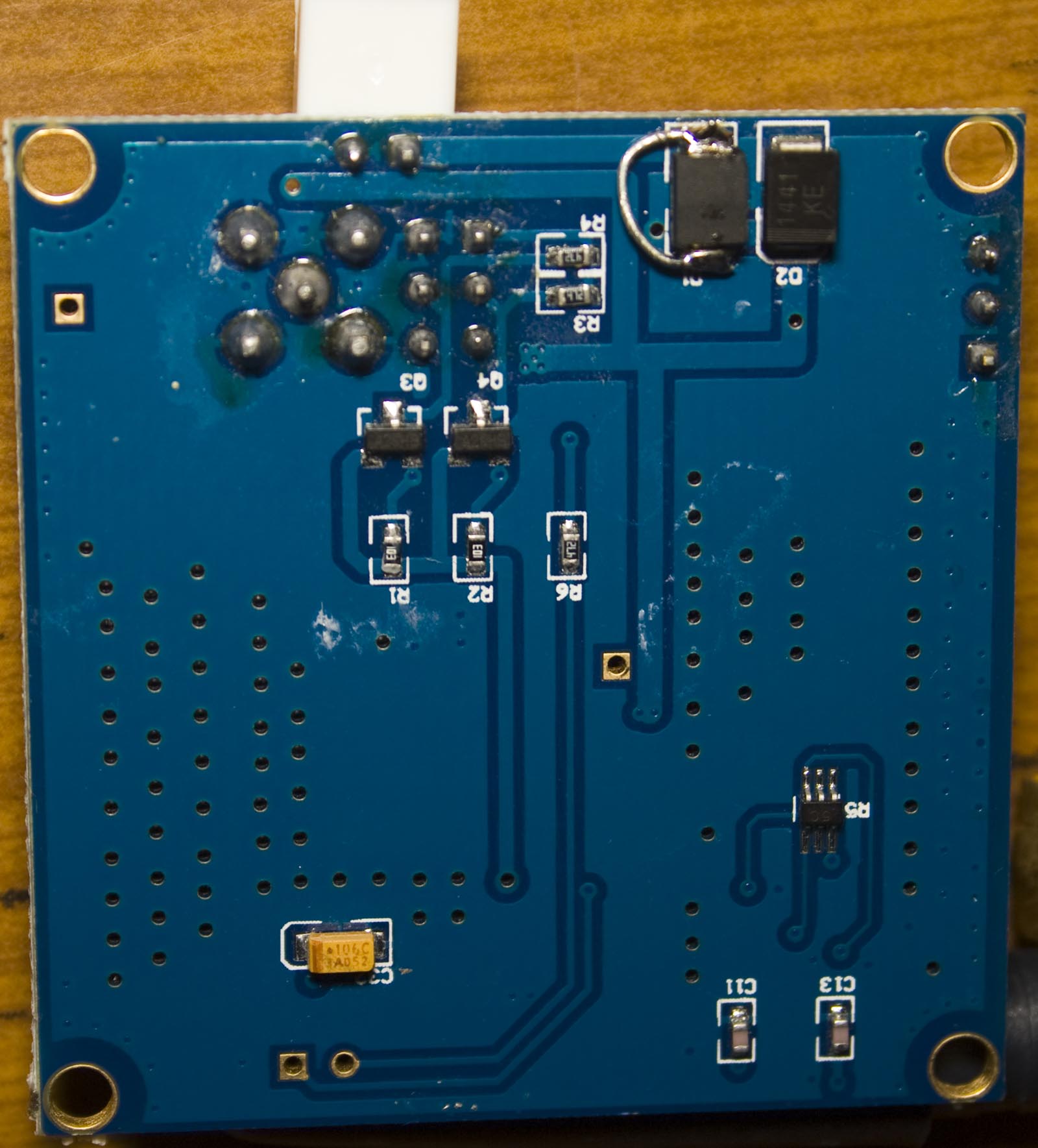
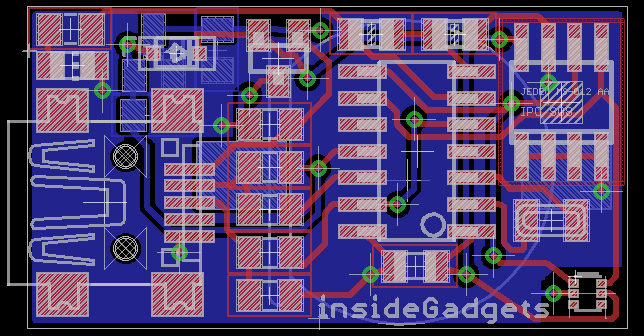
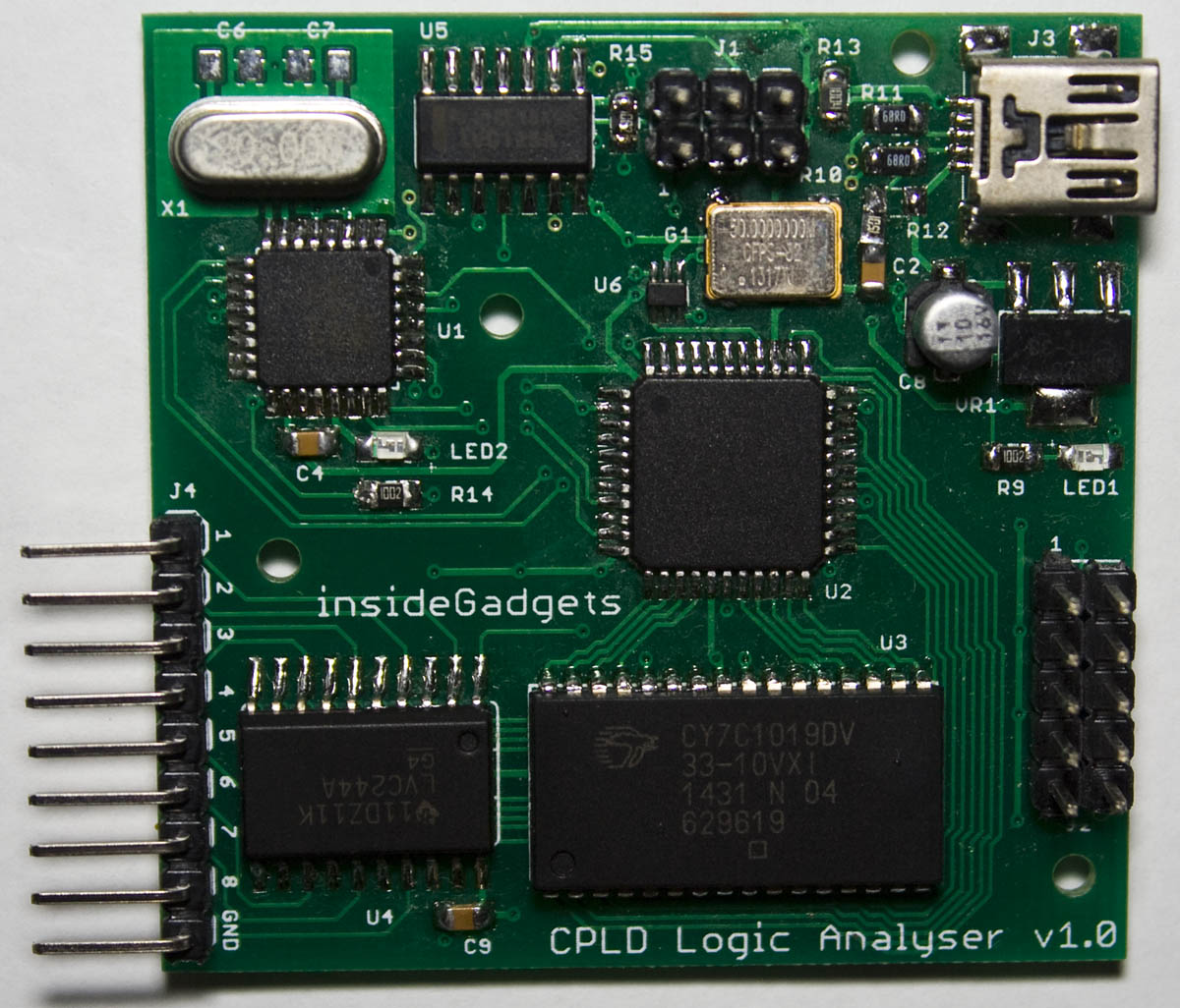
From our last part we added trigger options/sample rates, made small hardware changes and came up with possible design changes which could give us an 100MHz logic analyser. It’s been 6 months since my last update – I’ve just been working on little improvements and have enough that I can report on them all now. In this part we’ll take a look at our PCBs, move from MiniLA to Sigok Pulseview, a simple GUI interface and a few software modifications.
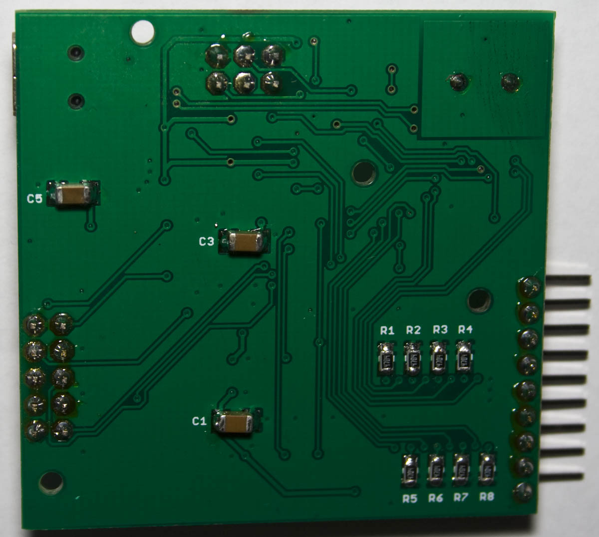
First things first, the PCBs arrived so I built one up quickly, the SRAM was a little tricky to solder and I reflow soldered the oscillator and Mini USB connector (I seem to always have issues with the pins bridging on the Mini USB when using an iron). Both the ATmega and CPLD were programmed successfully however the logic analyser just didn’t work properly. The CPLD was getting quite hot and turns out that some pins were stuck at VCC or GND no matter what I did and 1 pin on the ATmega also had an issue.
I found that the 1.5K resistor used for the USB was connected to 5V instead of the 3.3V regulator so potentially this could have caused the issue, good thing a cap with 3.3V was close by so I soldered it to that. I replaced the CPLD and jumper wired another pin on the ATmega to it and everything worked this time around. Just to be sure that everything was really ok, I built up a second PCB and confirmed it all worked.
I tested the logic analyser on a Gameboy cartridge and found that even when using 100K resistors, you could see a pretty bad load that its applied. I increased the resistors to 1M and then I settled with 4.7M.
Faster USB transfer
Previously I was using 2 bytes when transferring the 8 bits worth of data, the main reason being that I wasn’t able to use “0” as an actual result as it would mark the end of the string.
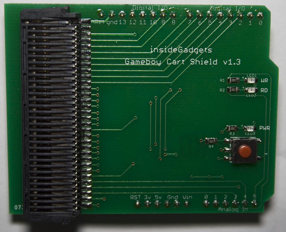
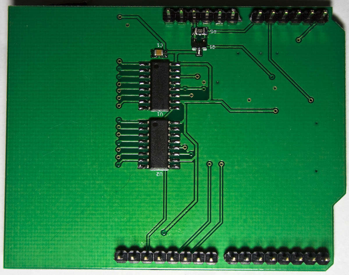
The Gameboy Cart Shield has now been updated to v1.3 which allows us to increase our speed by using SPI to communicate to the 74HC595 shift registers and also features a power button which allows us to switch cartridges without having to unplug the USB cable and supports the Gameboy Camera now. Previously I used to only provide the PCB / assembled version but I’ve decided that I’ll also start providing the kit version too now that there’s a bit more parts to it (will be in stock in 1-2 weeks).
I’ve had two users contact me with various improvements that could be made – the biggest ones were using SPI, increasing the baud rate, a cartridge sensor idea and a bug fix for reading the cartridge title so I updated GBCartRead to v1.6 to included these improvements.
Instead of using shiftOut, digitalWrite and the delay, we’re able to use hardware SPI to increase the speed and after testing the latch timing, 1 nop wait is all we need. I’ve replaced all digitalWrites and changing the DDR/PORTs directly for switching between inputs/outputs and high/low.
AdvanceVGA – Play your GBA on the big screen! Swap out the LCD for our board, solder some wires, connect 5V USB and VGA and you’re ready to go.
GBxCart RW allows you to backup GB/GBC/GBA ROMs, save or restore game saves and re-write supported flash carts. Mini RW option available for GB/GBC only.
Wireless Gameboy Controller – Use your Gameboy, mGB, GBC, GBA, GBA SP, GB Micro, NDS and NDS Lite as a wireless controller on Windows, Linux, Raspberry Pi, etc, and on your NES, SNES, N64, Gamecube and Wii.