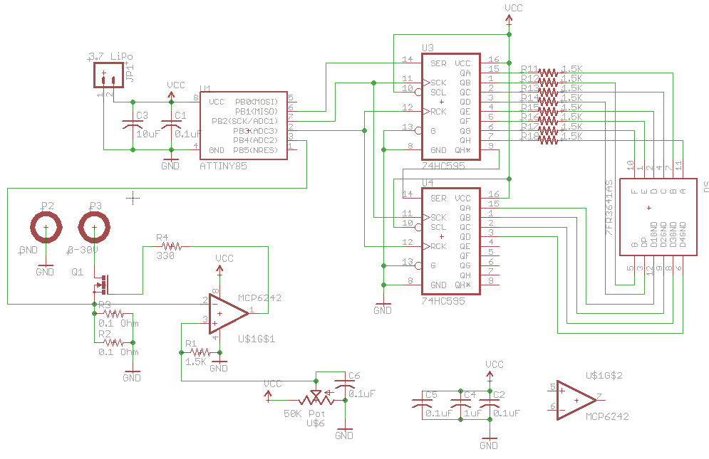
A while ago I built a simple constant current dummy load for testing my SMPS however the maximum load was about 1 amp and 2 amps with a fan on it and I always had to use a multimeter to measure the current. I’m looking at having a load of up to 4 amps or more, adding an ATtiny to control a 4 digit LED display to show the current, use a proper potentiometer and use a bigger heatsink.
https://www.youtube.com/watch?v=tWYfkr0ul5w
Originally I was planning to have it all powered by input voltage like before however at low voltages the STP22NF03L N mosfet that I had lying around didn’t switch on enough with the MCP6242 op-amp so after thinking about how I could do it – use 2x coin cell batteries, 9V battery, etc, I went with a Lipo battery. An upside of using a battery is that this allows us to use any input voltage between 0V to 30V to test our load with.
Before I had 1 ohm resistors which were almost getting as hot as the mosfet so I’ve gone down to 0.1 ohm 3W resistors – I added the option of another resistor in parallel if need be. I used a 1.5K resistor on the op-amp on the non-inverting side of the op-amp for a bit more fine tuning of the pot.
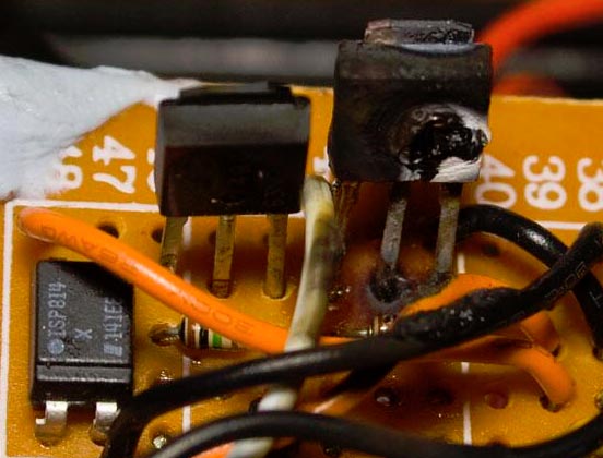
It was all working well until I decided to charge up the Lipo batteries to full which was just enough to voltage to fry (and catch fire) one of my high side mosfets from the voltage doubler (should have used boost strapping instead). Now it’s time for me to re-visit this project – use P & N mosfets, change the wireless to 433MHz for more range and add some controllable front/rear lights.
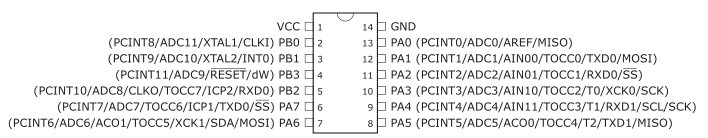
Originally I was going to use the ATtiny85 but since I want the lights to be controllable I need a few more pins so I’ll be using the ATtiny84. Most of the 433MHz receive/transmit code can be re-used from my Alarm system – Remote control upgrade and most of the rest could remain the same.
DDRB |= (1<<PB2); // Motor forward control
DDRA |= (1<<PA7); // Motor reverse control
TCNT0 = 0;
OCR0A = 0; // Sets motor forward duty cycle to 0%
OCR0B = 0; // Sets motor reverse duty cycle to 0%
TCCR0A |= (1<<COM1A1) | (1<<COM1B1) | (1<<WGM00); // PWM, Phase Correct and OCRA/B outputs
TCCR0B = (1<<CS01); // 8 prescaler
I decided to simplify the PWM to the motors and have it done all in hardware rather than using timers with interrupts like I did before.
From our last post we revisited the MC34063 circuit to see if improvements could be made in which we found reducing the turn off time helped quite a bit and we also made a constant current dummy load for testing. Also there was a user who left a comment about using a NPN, diode and resistor to improve switch off time, it reduced it by more than half and I saw 40C on the FDC365P mosfet. The MC34063 circuit has become a bit much as it stands in terms of the components/size so I went looking around for another DC-DC chip which costs around the same and is more modern.
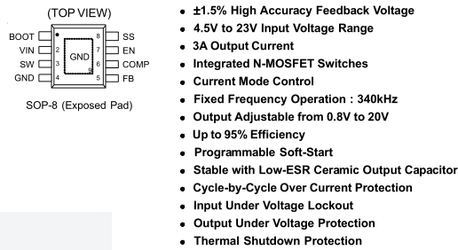
I found the Richtek RT8293A on special for 40c which is step-down converter, 4.5V to 23V input, 0.8V to 20V output, 340KHz operation and up to 3 amp output. There is a heatpad on the bottom of the SO-8 package for better heat dissipation.
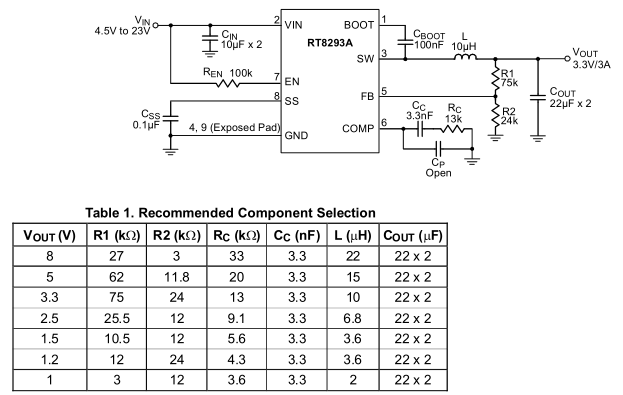
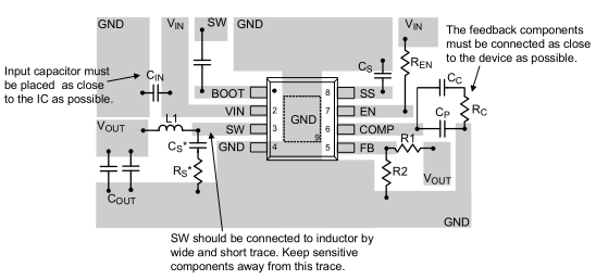
We adjust the output voltage by the resistor divider like before and since we are at a higher frequency we can use a small inductor though there are a few extra components to the RT8293A circuit too but they only add a few cents more to the cost. There is the 3.3nF and 13K for the error amplifier compensation, a soft start feature which uses a 0.1uF capacitor to slowly increase the output voltage, another 0.1uF capacitor to bootstrap the high side driver, a 100K for the chip enable and they recommend 2x 10uF input and 2x 22uF output ceramic capacitors.
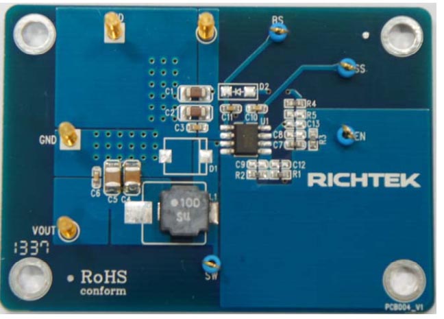
PCB Test
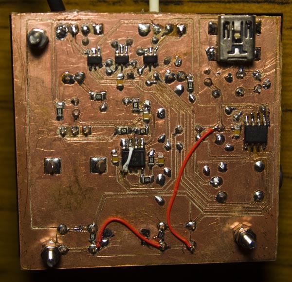
So I went ahead and bought everything that the datasheet said and started designing the PCB around the layout that they provided but looking around there is a reference board made more recently and the layout made a bit more sense so went with that.
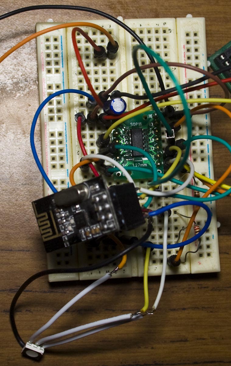
From our previous post, the cases/mounts were built, a few more smaller changes were made and we added in the SMS capability. I thought that was the last change I would do to the alarm system for a long time but it turns out that the range of the remotes using the nRF24L01+ wasn’t very good, when outside the house you had to be within a few metres. This time we’ll be looking at adding 433MHz wireless to our system for the remotes to improve our range.
https://www.youtube.com/watch?v=mlmMsxs-U5Y
(sneak peak)
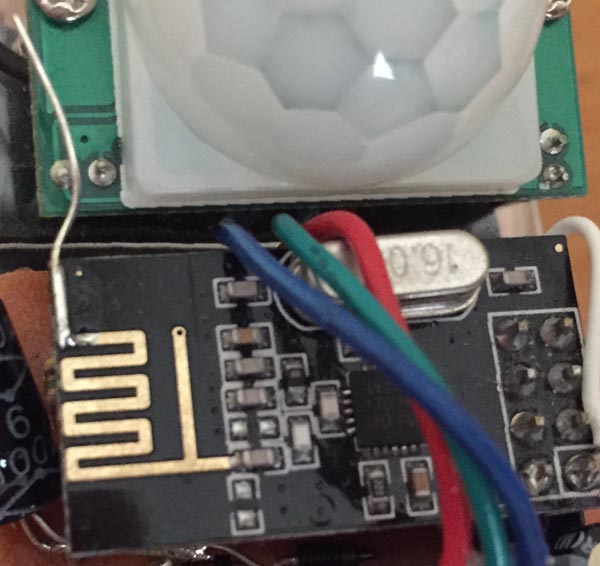
When I found the remotes range wasn’t great, I tried switching to 250Kbps operation of the nRF however I found that firstly there was an issue with the PCB antenna, sometimes it would work fine but other times I had to touch the antenna and then it works.
I added in a extra bit of wire to the antenna and that sorted it out though the range didn’t really improve much and by that time I had already switched the door/PIR sensors to 250Kbps too so I was stuck with it. So I needed a solution – could I possibly re-wire the old alarm system remotes to transmit the data I want?
Previously I made a small solar power garden light with an RGB LED controlled by an ATtiny13 and I have been thinking about how I could create a different project from it. The ability to control these RGB LEDs via wireless on demand seemed like an interesting idea – potentially you could program a sequence and have them execute it to give you a small light show if you had enough of them.
(sneak peak)
After browsing for an AVR, I found the ATtiny841 that has 3 timers which is exactly what I need to control each LED properly with PWM (another solution would be to use a WS2812 LED).
Each ATtiny841 was $1.3 so you can’t really go wrong, I didn’t know these MCUs were available so it’s a good idea to regularly browse supplier’s websites for new products. For the server side, I’m thinking an ATmega with 16×2 LCD and keypad to enter the sequence.
Client side
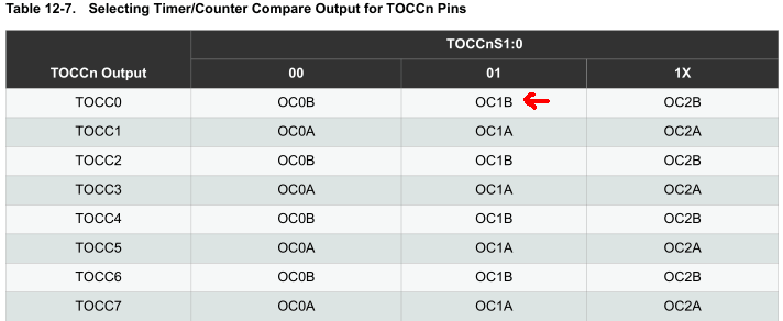
The ATtiny841 gives us the ability of selectable output pins for the timers which you’ll need to configure to have any output from the timer at all plus you also need to enable the timer output enable of the pin too.
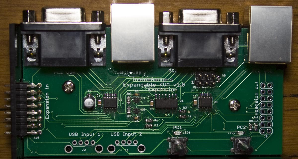
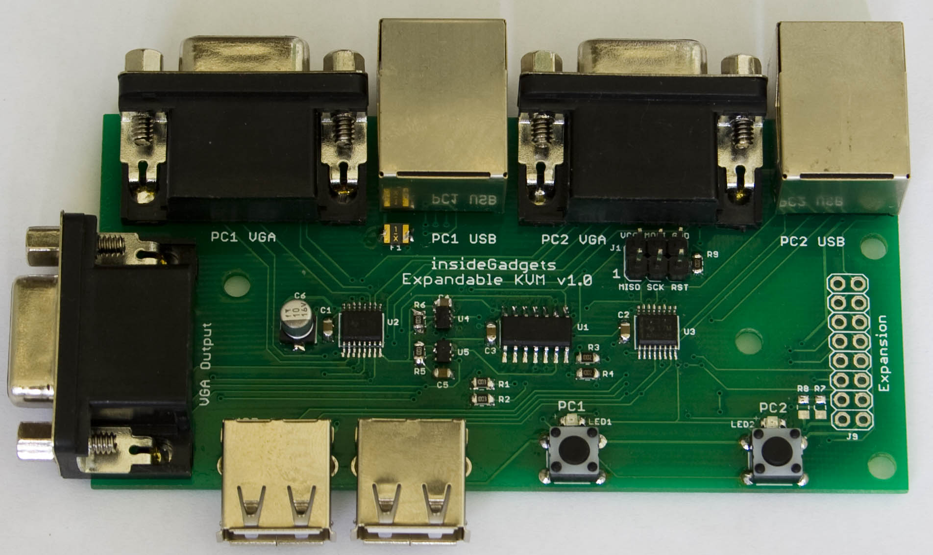
From our last part we moved over to the ATtiny24, our PCB arrived, tested good and made a quick case for it. This time we’ll check out the expansion board, a new case with changes needed to make the case work and the KVM board is now available for purchase.
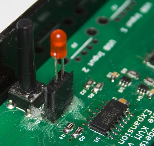
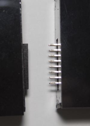
The expansion board has arrived, it’s basically the same as the main board except it’s got a input expansion port instead of the VGA port. One thing I forgot to take out was the USB ports for the expansion board, so potentially if you didn’t want to use the main board’s USB connectors you could use them (I’ll take them out of the next version).
I bought some 20mm buttons and was able to solder in a 2 pin female header on the LED SMD pads so I could attach a 3mm LED to it and added some glue to hold it all in place.
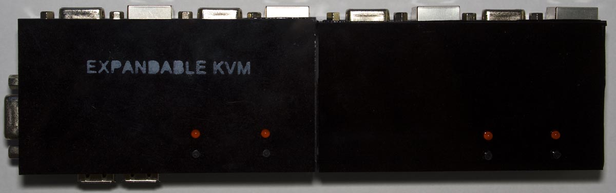
After changing the case colour to black it looks nicer and after connecting the expansion board with case too, it fits pretty well and it works. I need to put some labeling on it, the only viable method I’ve found so far was to make my own stencil from acrylic and then spray paint the name on it, you have to do a light spray otherwise it’ll seek through the stencil.
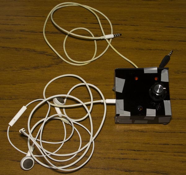
At work, we use Snom phones and we take quite a number of calls every day, when you use the handset and need to type it’s a bit difficult. There are some headset/headphones options available, the Snom uses 4P4C / RJ9/RJ10 connectors but I’ve always got my iPhone headphones on, so I’d like be able to use them on the Snom phone.
(sneak peak)
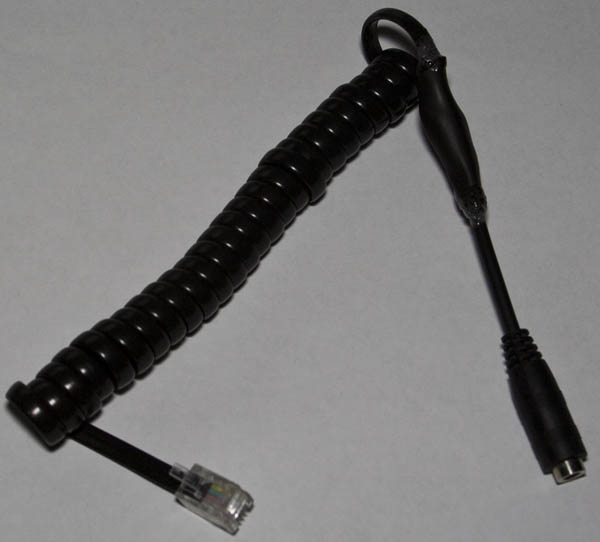
The first step was to build a Snom 4P4C to TRRS cable, I used a 220 ohm resistor for protection to find the left/right speakers and then used a 1.5K resistor for the microphone.
It turns out that the microphone was a little hard to hear so after removing the 1.5K resistor it sounded better but it wasn’t loud enough unless you place the mic close to your mouth.
After speaking with a colleague, the idea came about of being able to switch between an iPhone and the work desk phone easily, it shouldn’t be a problem since we can an analog switch to do this. I had the Ti SN74LVC1G3157 SPDT switch on hand and it should do the trick, just hook up 3 of these for the mic and speakers.
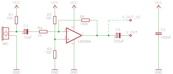
Now it’s back to making a boost circuit for the microphone, I looked around for a low cost op-amp and found the LMV358 which is just like the LM358 and it’s rail to rail. I found an LM358 op-amp inverting circuit which we’ll use to start off with (shown above). I firstly tried a non-inverting opamp configuration but it didn’t turn out to be as good as the inverting one above. The configuration above boosts the microphone’s output (which is AC coupled) by 100x and the 10K/10K divider on the non-inverting side keeps the opamp’s output at half of VCC so that when sounds are produced there will be an AC waveform (e.g with VCC/2 being 2.5V, we could get a waveform that goes 1.5V to 3.5V) just before the 220uF capacitor.
From our previous post, we made a small number of changes and started building acrylic cases/mounts for some of our boards. This time the cases/mounts have been build, a few more smaller changes and add in the SMS capability.
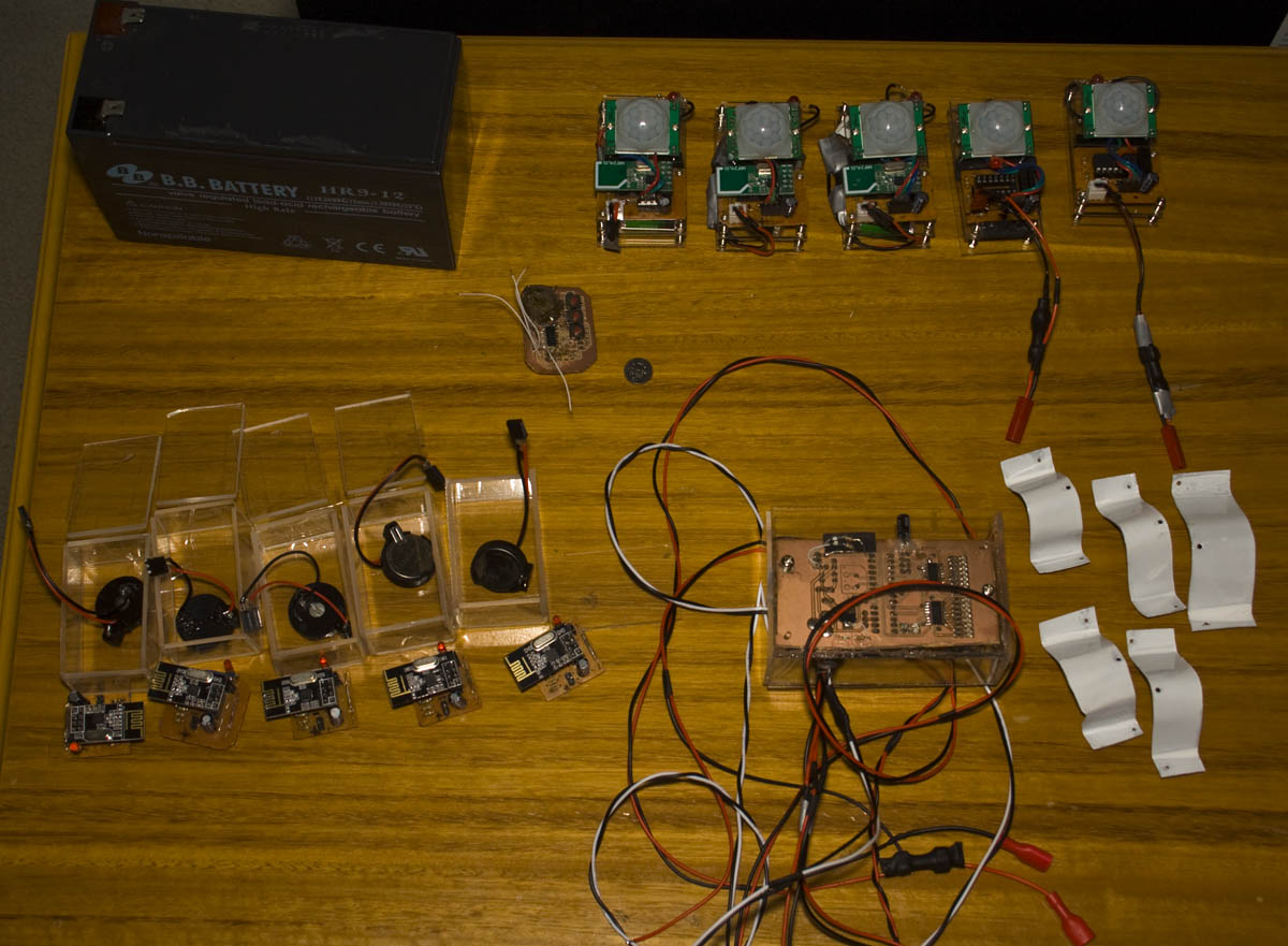
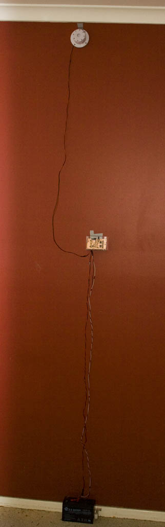
Here’s how everything looks at the moment – ready for deployment. I’ve got cases for the PIR, door sensors and the alarm system server which I’m planning to mount to the wall, connect the leads to the battery/adapter on the ground and the siren near the ceiling.
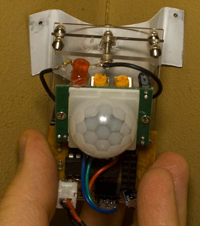
One problem that I’ve been able to find a simple solution to is how to mount the PIR on the corner of the wall like my current alarm system does. I’ve found that a 0.5mm aluminum sheet is flexible enough to cut with tin snips, mold into a U shape and it will keep it’s shape.
A year or so ago I decided to make a smaller version of the Standalone Temperature/Voltage Logger which would only do temperature called the A25TTL which measured 17mm x 12mm. In this post, we’ll be updating the A25TTL to v1.1 so we can use any EEPROM, v2.0 so we can now also use an ATtiny13 and briefly show my new programming method for SMD ATtinys.
V1.1
At the time, I used the cheapest 512K EEPROM I could find (the ST M24512) however I found that not all EEPROM’s SCL/SDA lines acted the same and I had run the ADC a few times to determine if the logger was connected to the reader – not the best way to do this. I recently found that the M24512 EEPROM doubled in price so this was the main reason to update to v1.1 which makes the logger to set it’s pull up resistors on the SCL/SDA lines at boot which means that we can now use any EEPROM.
PORTB |= (1<<TWI_SDA_PIN) | (1<<TWI_SCL_PIN);

watchdogSleep(T1S); // Wait a little bit for things to settle

// Check if we powered up from the USB port
if (!(PINB & (1<<TWI_SCL_PIN))) {
	system_sleep(); // Sleep forever
}

PORTB &= ~(1<<TWI_SDA_PIN) | ~(1<<TWI_SCL_PIN);
...
This not only helps some EEPROMs reducing the current they draw but puts the ATtiny’s pins as inputs thus allowing the reader to pull SCL low. The logger waits 1 second, reads the SCL pin, if it’s low it goes to sleep otherwise it starts logging.
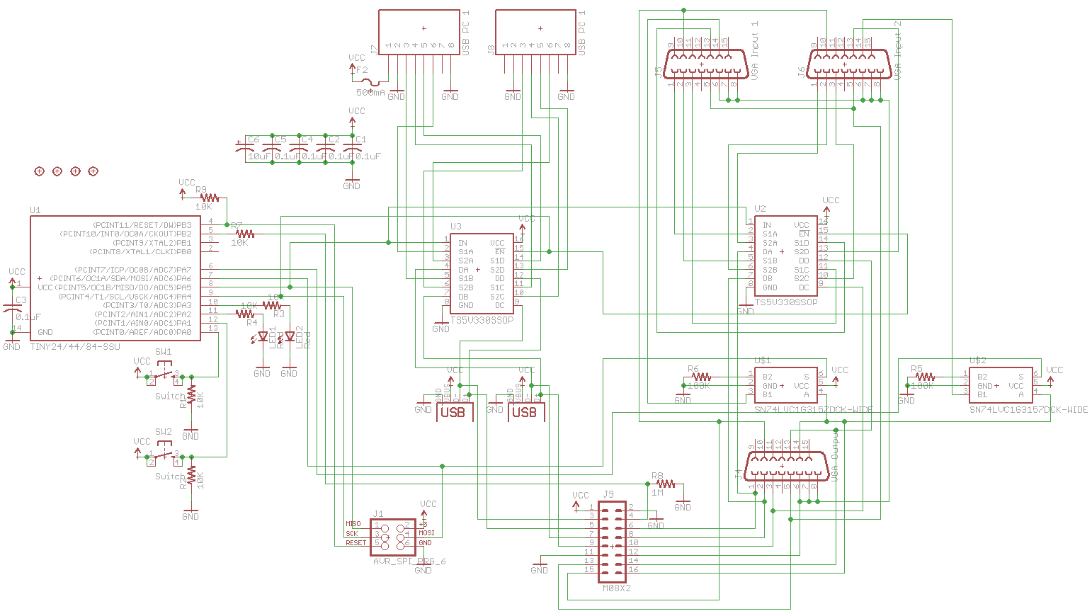
From our last part we made a PCB prototype and looked into how we could expand past two ports using 7400 series logic but in the end it’s easier to use an ATtiny to do this which we’ll take a look at this time plus the PCBs have arrived and I’ve made a case for it.
I went with the ATtiny24 which gives us enough pins to turn on both LEDs, monitor both switches, switch the enables and inputs high or low on our analog switches. After playing around with the expansion line concept which each ATtiny would be connected to, a 1M resistor to ground and 10K resistor to the ATtiny pin to protect it works well.
After combining both boards together into one, we have the schematic above. I’ve added the polyfuse, 2x of the SPDT analog switch with a 100K resistor to ground to make 1 side be high impedance, added a programming header, have 0.1uF capacitor on each IC and added a 10uF aluminum SMD capacitor to help with smoothing the power which would eventually go to the expansion boards and to also offer a little bit of voltage spike protection.
AdvanceVGA – Play your GBA on the big screen! Swap out the LCD for our board, solder some wires, connect 5V USB and VGA and you’re ready to go.
GBxCart RW allows you to backup GB/GBC/GBA ROMs, save or restore game saves and re-write supported flash carts. Mini RW option available for GB/GBC only.
Wireless Gameboy Controller – Use your Gameboy, mGB, GBC, GBA, GBA SP, GB Micro, NDS and NDS Lite as a wireless controller on Windows, Linux, Raspberry Pi, etc, and on your NES, SNES, N64, Gamecube and Wii.