On Mothers day, I had this idea that it would be fun to make a little LED heart to light up with various animations and would be powered from a coin cell. The board would just be about the same size as the coin holder.
(sneak peak of the end result)
The first step was choosing the MCU, we could go with an ATtiny84 and have an LED on each pin but it’s fairly big, an ATtiny25 with shift registers would work but that would take up most of the board. We can use a technique in which you could configure a series of LEDs in such a way that you only need a few pins to control more than double the LEDs when you reach 4 pins – it’s called charlieplexing.
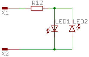
By configuring both ports as outputs and having one source current and the other one sink current we can effectively control both LEDs depending on which port does what. To calculate how many LEDs an number of pins can control you can use the formula (n2)-n, so for 4 pins we could control 12 LEDs. When you have 3 or more pins, you need to tri-state the pins that aren’t been used otherwise you may have the wrong LEDs light up.
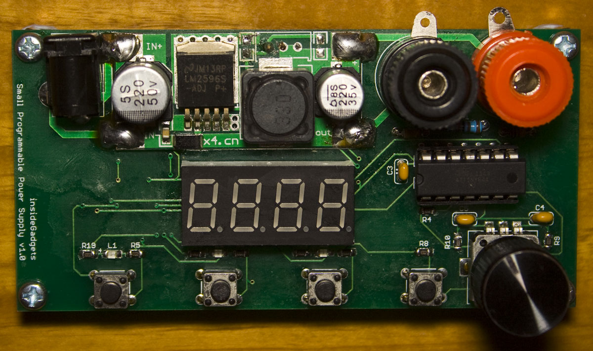
I’ve finally gotten around to releasing the Small Programmable Power Supply (SPPS) v1.0 which I made at least 6 months ago. The SPPS uses the LM2596 module found on Ebay with an ATtiny44 and digital pot to enable adjustable output voltage using a rotary encoder and allows you to have 3 programmable buttons to store preset voltages that you can switch to easily.
There is only limited stock for the time being of the full kit just to see how it sells, the full kit is $29 AUD with $7 shipping (as it’s over 50 grams) and $7 for the PCB only.
From our previous post, we made our remote control and looked at making some improvements however we ended up going back to how sensors communicated to the server before. This time we’re building our prototype PCBs and get to test them all out.
(sneak peak of our PCBs working together) .
Server PCB
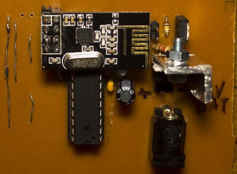
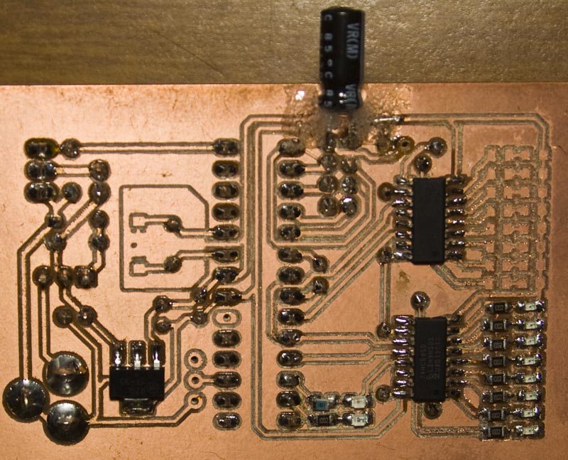
I wanted the server to have a battery backup along with a siren so I took a 15V power adapter and wanted to have some LEDs to display which sensors have checked in with some shift registers to make things easy and now we can have up to 16 sensors. There is also a green LED and red LED used for communication pass or fail, I should of put another LED to shown when the alarm is on. After about a minute or so, the sensor LEDs are reset.
I used the LM317 to reduce the voltage down to 13.5V which is the floating charge voltage for a 12V SLA, the 15V input barely cuts it for 13.5V and doesn’t provide too much current, about 50mA or so. In the end it does run a bit hot so I put in a metal piece on it I had lying around which works good enough. We’ve got a LDO to provide 3.3V to the ATmega328 and nRF24L01+ module, it too runs a bit hot, should have given it more copper. I ended up tearing the pads for the capacitor which is why it’s bodged in there like it is.
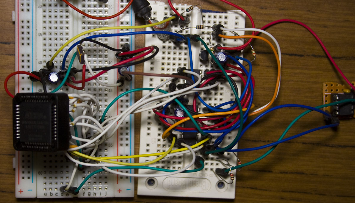
From our last part we looked at testing the idea with the EPM240 board, in this part we’ll switch over to the EPM3064 CPLD to move away from the development board.
The Altera EPM3064ALC44-10N is a low cost 100MHz CPLD for $3 in a PLCC 44pin package with 64 LEs and 34 usable pins. The oscillator I’m using is 50MHz which I pulled from another board and all we need is to connect it to VCC, pull it’s enable pin high and that’s it. I was curious about how much current it consumed, it was about 13-15mA.
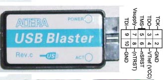
We can connect our USB Blaster to our CPLD by connecting up the 4 wires, TCK to TCK, TDI to TDI, TDO to TDO and TMS to TMS; as you can see you don’t connect them together like you do for the MISO of one device the MOSI of the other.
From our last post, we connected 4 hard drives with SATA to USB controllers to our Raspberry Pi with an LCD and were able to assemble our RAID5 array. Now we’ll be looking into putting it together into the Netgear ReadyNAS enclosure, powering on/off with a relay, temperature monitoring, backup/activity LEDs, and so on.
(sneak peak of the NAS4Pi built)
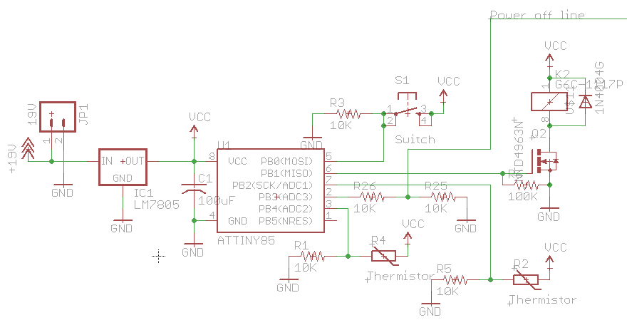
Relay for power switch, RPi power off and temperature monitoring of mosfets
To be able to switch on and off the NAS4Pi, I’ve hooked up a relay which is using ATtiny25 that switches on the SMPS. The only issue is that we need to give the relay 5V at 80mA, so I’ve just put on a LM7805 with a heatsink to power the ATtiny and relay and it’s temperature hovers around 50C or so. One thing I didn’t notice with relays initially was that you should have a diode connected up to the coil because otherwise when you switch off the relay you’ll have some backEMF.
When we’d like to switch off the RPi, we shouldn’t just switch the power off at any time instead we’ll use a power off line which when it goes high will tell the RPi to shutdown and we will wait about half a minute for it to shutdown before switching the relay off.
From our previous post, we took on the task to build our own alarm system and have the PIR, door sensor and some of the server code built. In this part we’ll add the remote and look at some attempted improvements.
https://www.youtube.com/watch?v=MYtkCsHhZ0Y
(sneak peak of remote, PIR, siren and server all working together)
For the remote control, all that’s required is two buttons for alarm on and off plus an LED to show when the button is pressed.
// Increment our 256bit random number
...

// Generate the random block (160 bit) using SHA1 from our random number
sha1(data_out, random_number, 256);

// Set data_out to say we are a remote control
data_out[SENSOR_TYPE] = REMOTE_CONTROL;
data_out[REMOTE_REQUEST] = REMOTE_ROLLING_CODE;

// Check in the with server
if (check_in()) {
	...
	// On or off?
	data_out[SENSOR_TYPE] = REMOTE_CONTROL;
	data_out[REMOTE_REQUEST] = system_state;

	// Generate the new rc code to use and generate the SHA1 block (160 bit) from our rc code
	rc_code_init(rc_code_addition);
	sha1(data_out, rc_code, 128); // SHA1 of our rolling code

	// Transmit a few times to ensure the server gets it
	...
}
We can use the same PIR code to send a random SHA1 block, receive the rolling code addition which will be 32bit this time to cover switching the on/off alarm a lot of times and then we’ll quickly send the rolling code a few times.
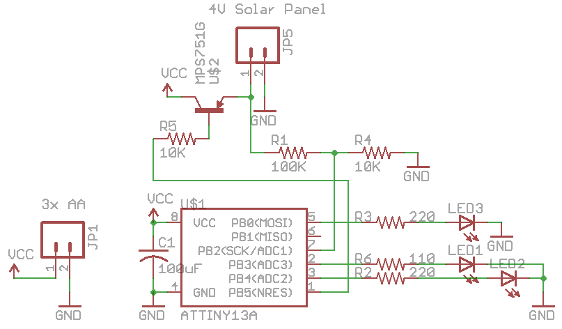
After seeing a few solar garden lights as a quick project I decided to make my own version using the ATtiny13A so it can be low cost but have decent functionality. I didn’t an RGB LED so I went with red, green and yellow LEDs and in terms of the solar panel I have a 4V 50mA one.
(sneak peak of the end result)
My first initial thought was to use a Lipoly battery to power everything, use a diode with the solar panel to recharge the battery with an LDO to 3.7-3.9V if needed. My main concern is leaving the Lipoly outside and it heating up quite a lot so I’ve decided to go with AA batteries.
After a few iterations of the design, I went with 3x AA batteries to be recharged and the charging will be switched on using a PNP transistor, I’m going for 1.4V per AA battery. Originally I wanted to go with a N or P mosfet however since the Vds would be less than 1V so it wouldn’t be able to switch on. One unintended feature of the PNP design in this case is that it’ll automatically charge up the 3x AA batteries if they are 0.6V lower than the solar panel.
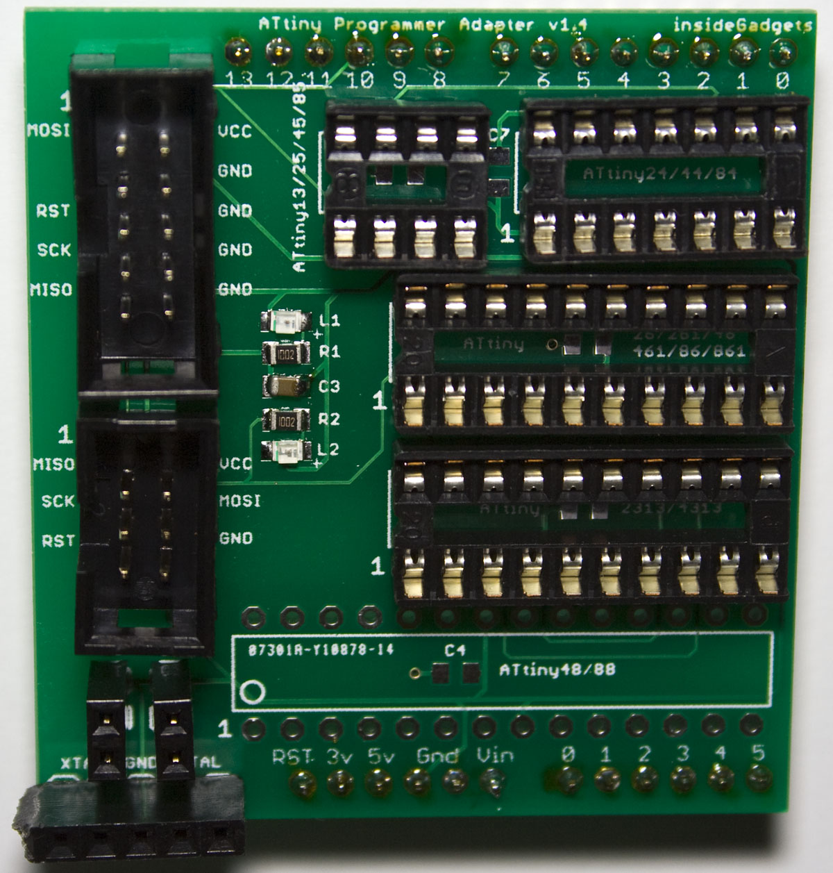
The main feature is that you can now add some male headers and convert it into an Arduino shield so you can program your ATtiny with your Arduino if you don’t have a dedicated programmer.
I’ve added another LED for the MISO so if this LED lights it means that your ATtiny is able to communicate with your programmer. Another small improvement was to move the 6 and 10 pin headers a bit more apart so that you can fit in IDC socket connectors.
Previously I made a ATtiny GPS Long Lat logger to record the GPS co-ordinates to an EEPROM and now it’s time to implement the full functionality of my project which is to check an accelerometer for motion, monitor the GPS until we are in a certain area and then send an SMS. If it’s a few KM away from the area, then it’ll turn the GPS off for a few minutes and check again later but if it’s close to the area, it will keep checking the GPS as long as movement is detected within 1 minute.
https://www.youtube.com/watch?v=JNAqu732Uqw
I was using the ATtiny2313 before however it didn’t have any ADCs so I’ve switched to the ATmega88 which is approximately the same price. To reduce power I have a mosfet for the accelerometer, GPS and mobile phone. The mobile I’m using this time is the Nokia 3210 which cost me $22 from Ebay, the battery seemed to discharge after a couple of days so I was trying out different options.
//  Reset  PC6  1|o   |28  PC5 N Mosfet for MMA7361 accelerometer
//  RX GPS PD0  2|    |27  PC4 N Mosfet for GPS
//  TX SMS PD1  3|    |26  PC3 N Mosfet for Nokia 3120
//         PD2  4|    |25  PC2 X Axis
//         PD3  5|    |24  PC1 Y Axis
//         PD4  6|    |23  PC0 Z Axis
//         VCC  7|    |22  GND
//         GND  8|    |21  AREF
//    XTAL PB6  9|    |20  AVCC
//    XTAL PB7 10|    |19  PB5 SCK
//         PD5 11|    |18  PB4 MISO
//         PD6 12|    |17  PB3 MOSI
//         PD7 13|    |16  PB2 Optoisolator for Nokia 3120 power button
//         PB0 14|    |15  PB1 LED
The Nokia 3210 seems to power up from ~2.3V to 3.4V, so one option is to try a 3.7V Li-ion with a diode to drop it however after some experimentation it switches only stays on for a few seconds.
A little while ago I had a Netgear ReadyNAS unit which was faulty and wasn’t able to repair it however I thought it would be worth re-using the case to make my own NAS using the Raspberry Pi. I decided to build my own SMPS to provide 5V and 12V to the drives and the Pi and I’m using USB hub with 4x USB to SATA adapters to connect to the 4 hard drives.
https://www.youtube.com/watch?v=-9CjN0F9VXo
(how it all looks at the moment)
After hooking up an 16×2 LCD display to the Pi, I made a start up script in Python to check the drives, assemble the array, mount it and then display the RAID status and free space (see the video above).
AdvanceVGA – Play your GBA on the big screen! Swap out the LCD for our board, solder some wires, connect 5V USB and VGA and you’re ready to go.
GBxCart RW allows you to backup GB/GBC/GBA ROMs, save or restore game saves and re-write supported flash carts. Mini RW option available for GB/GBC only.
Wireless Gameboy Controller – Use your Gameboy, mGB, GBC, GBA, GBA SP, GB Micro, NDS and NDS Lite as a wireless controller on Windows, Linux, Raspberry Pi, etc, and on your NES, SNES, N64, Gamecube and Wii.