Posted in Teardowns on Dec 8th, 2014
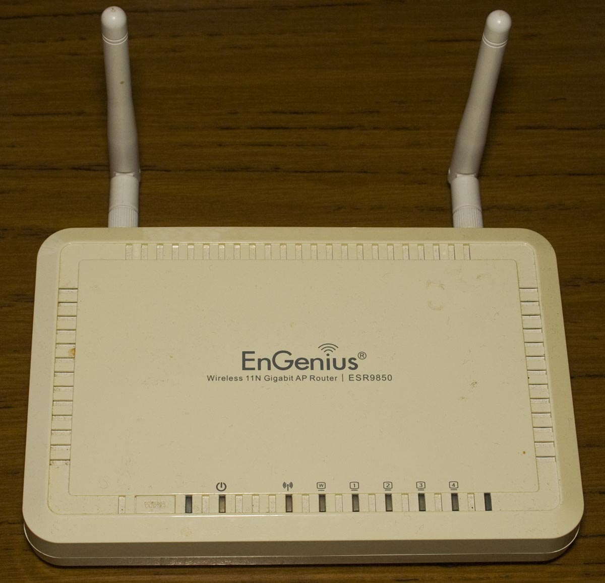
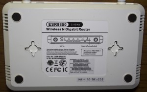
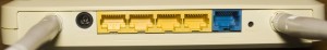
Today we’ll be taking a look at the EnGenius ESR9850 Wireless N Gigabit Router, a wireless router with 4 gigabit ports, haven’t heard of this brand before.

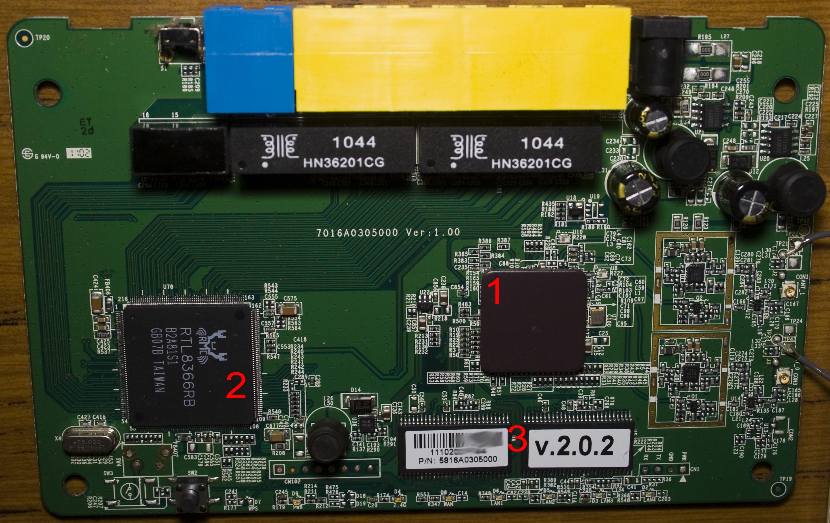
4 screws later and we’re in.


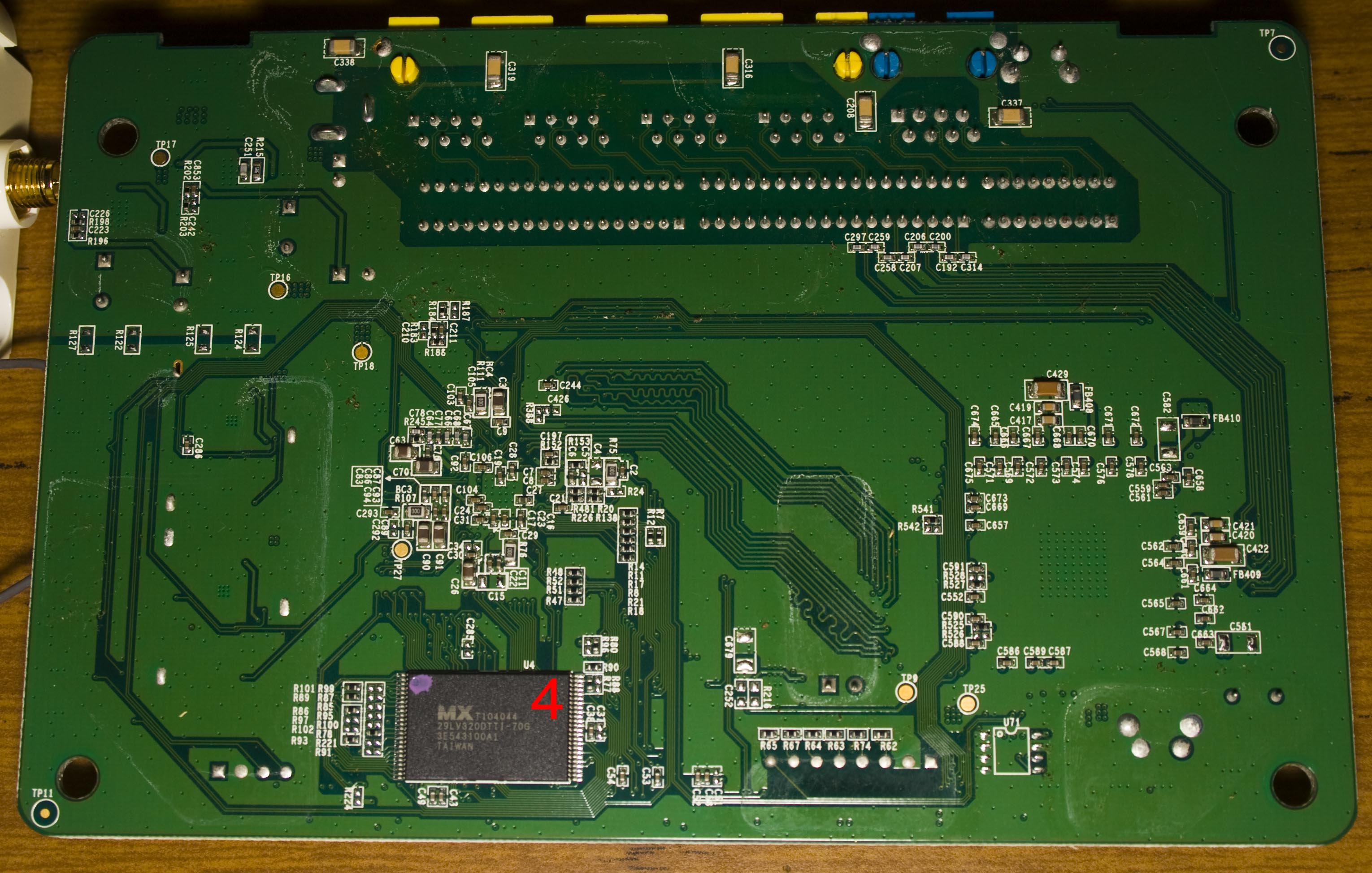
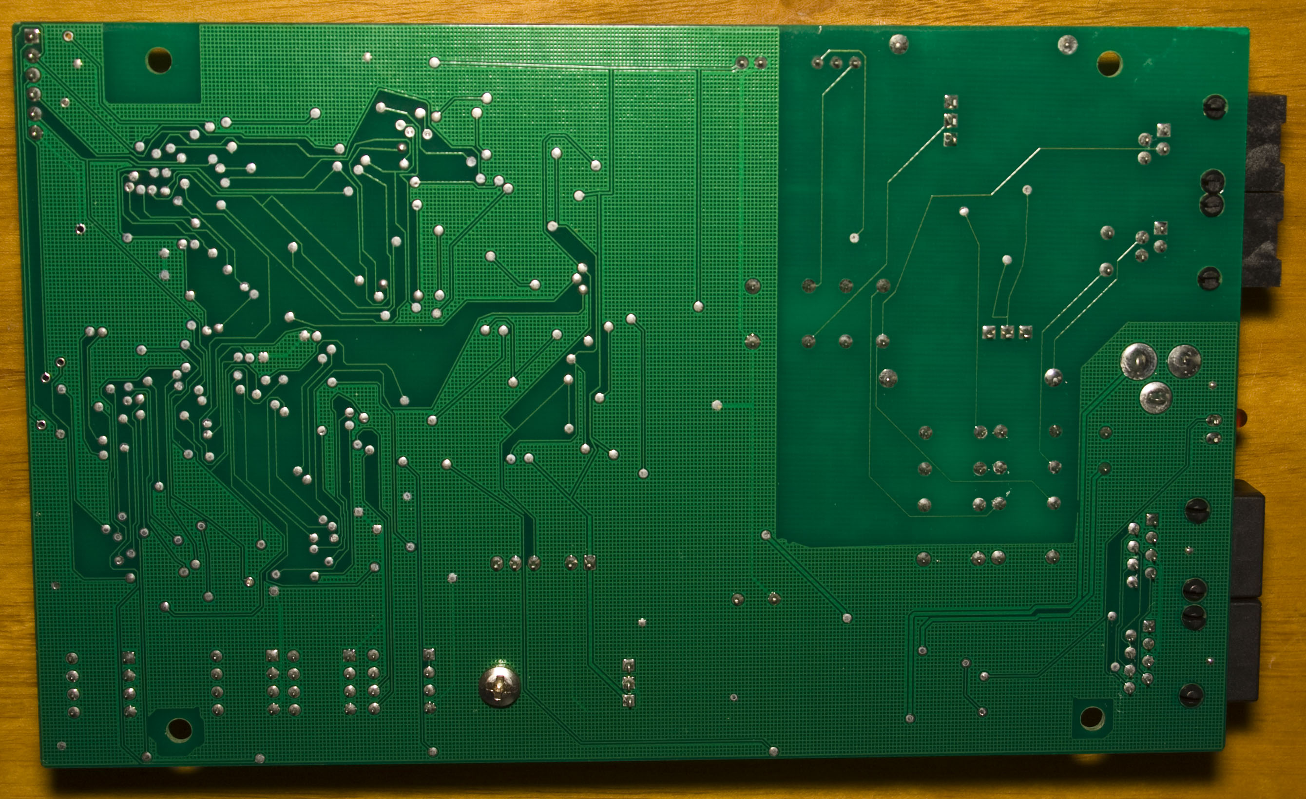
PCB layout looks quite good, we’ve got a ceramic heatsink on the main processor, 2 RF outputs without the metal cans with the antenna cable soldered on, 2x CAT7125CA SMPS up the top right plus a smaller U8AM878 one near the bottom center and a TX/RX unpopulated connector and an 8 pin unpopulated connector – likely JTAG. PCB date code is 2nd week of 2011.
(more…)
Read Full Post »
Posted in Teardowns on Nov 20th, 2014
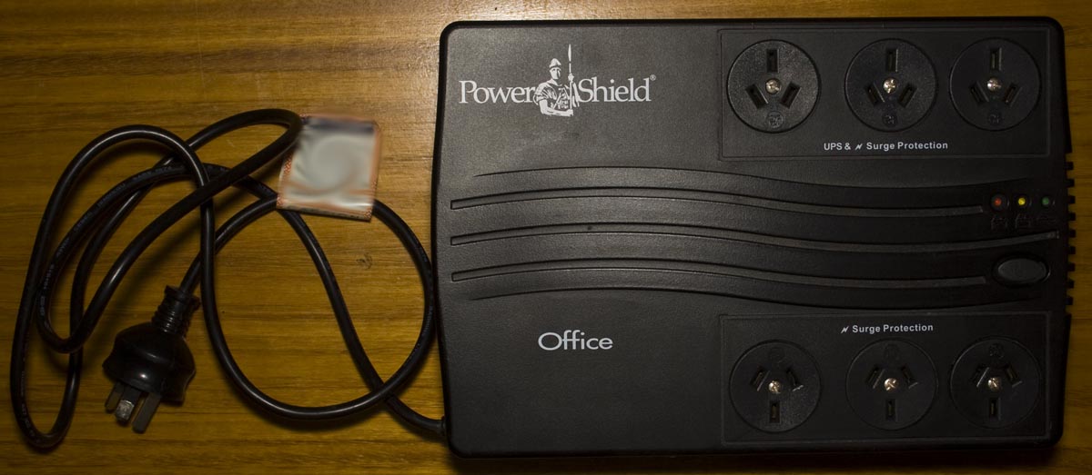
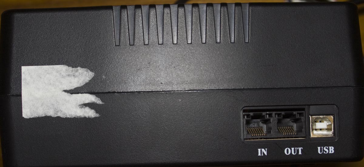
Today we’ll be taking a look at the Power Shield PSO-650 650VA Powerboard UPS, a 3+3 output UPS with surge/battery protection, phone line protection and USB for monitoring it on your PC. This particular unit failed because the 12V battery dropped to around 2 volts.
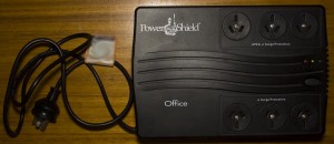
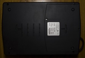
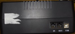
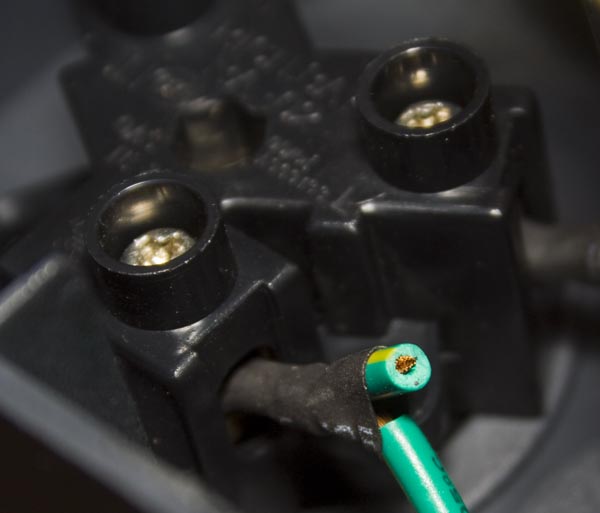
By looking at the power cord is going to tell us that this UPS is going to be built down to a price because the cord comes straight out of the UPS itself.
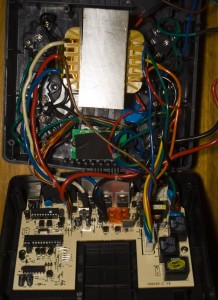
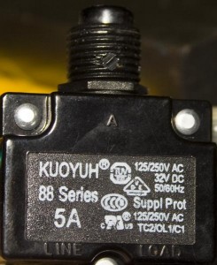

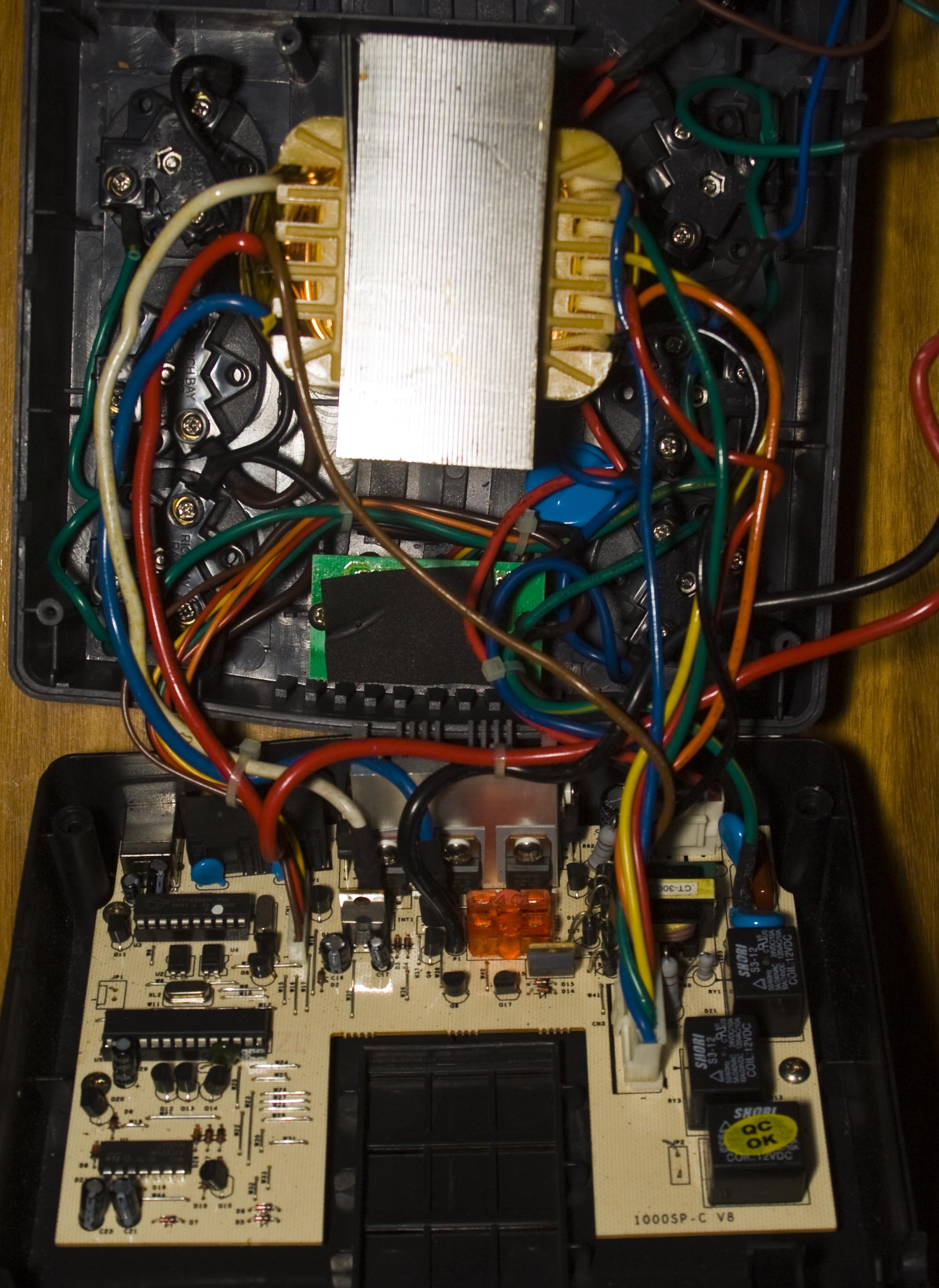
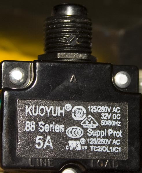
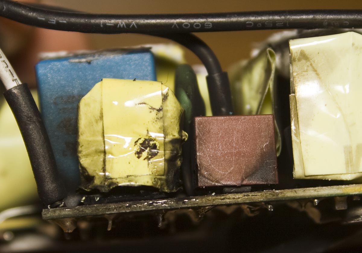
We’ve got our main PCB on the bottom and a huge transformer on the top which isn’t glued or bolted down, it just sits there due to the pressure the case puts on either end when closed. We have a 250V 5A circuit breaker on one side of the case. The surge protected outputs have some big MOVs on them. There are a few things which could be a little better, the heat shrink may have been too big that it’s pretty easy to move around and they left in an extra wire like it was meant to go somewhere else (not that it matter too much as the terminals screws are exposed anyway). The transformer is a 1065SP-2-V8/ E186x40.
(more…)
Read Full Post »
Posted in Teardowns on Nov 16th, 2014
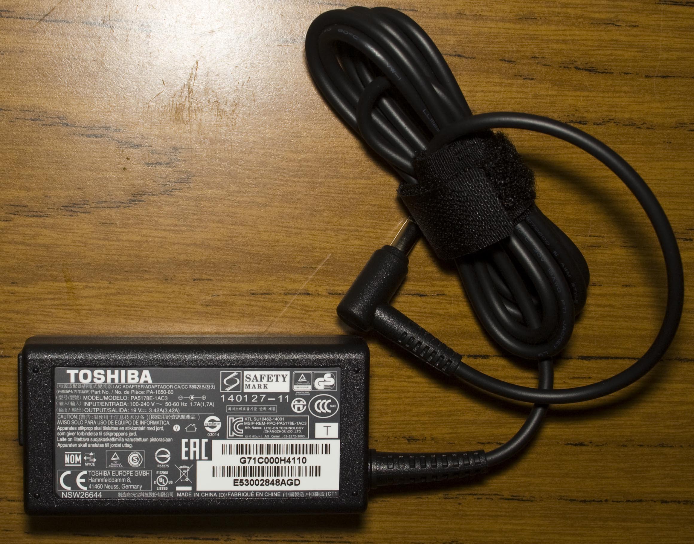
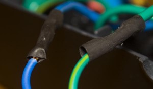
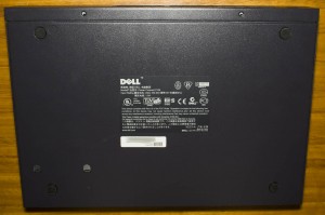
We recently purchased a Toshiba Satellite Pro L50 for a client, took it out of the box and started setting it up. About 2 hours later, I hear a bang and the circuit breaker trips. After smelling the power adapter; it smelt bad so it was likely blown, it was sitting about 1 metre away from me. Luckily the laptop survived and to Toshiba’s credit they sent a power adapter which arrived the next day (I left it running for 24 hours without issues).

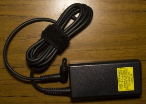
The power adapter is a 19V 3.42 (model PA5178E-1AC3, part PA-1650-60).

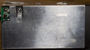
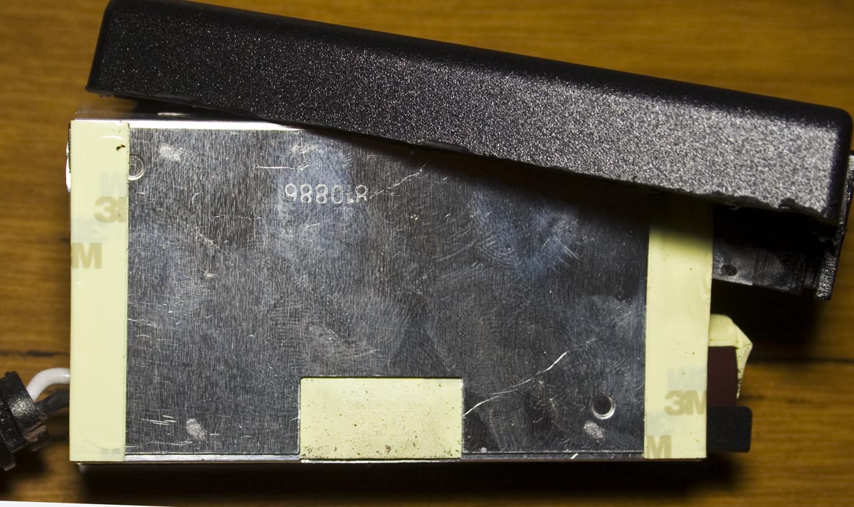
After taking a dremel to the plastic casing, we’re in. The metal shielding is connected to earth via a 1K resistor. So far no signs of damage.


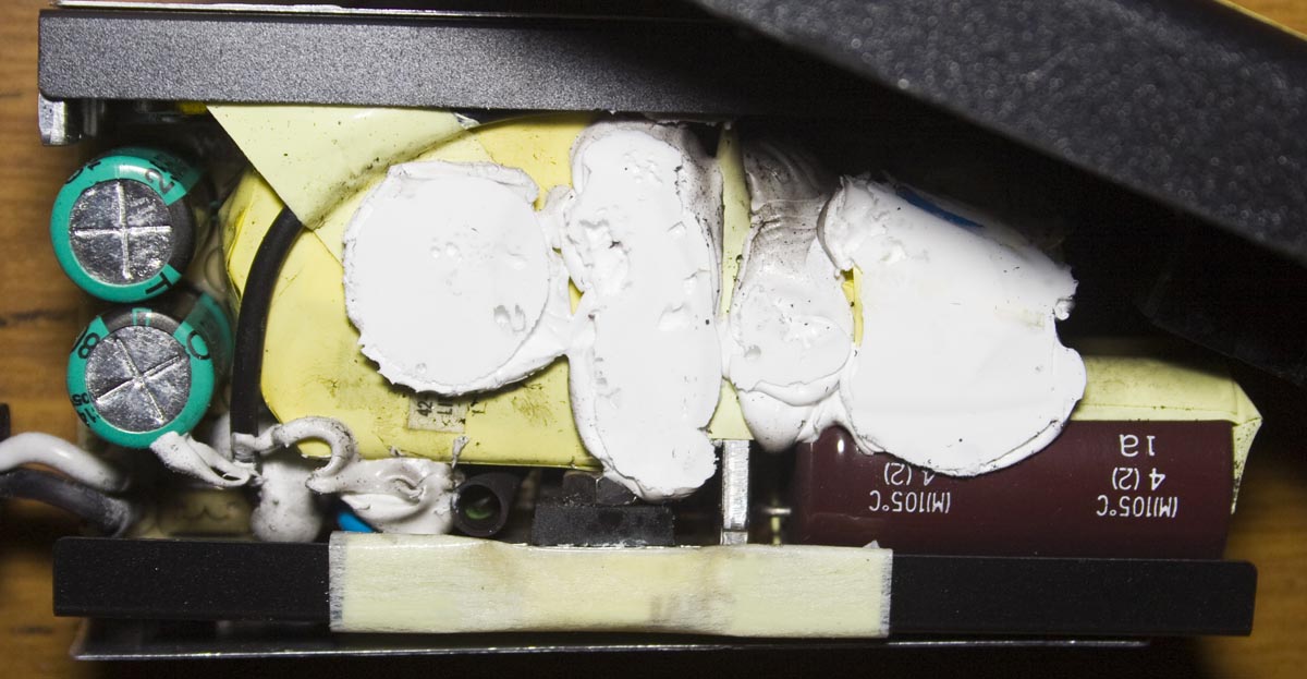
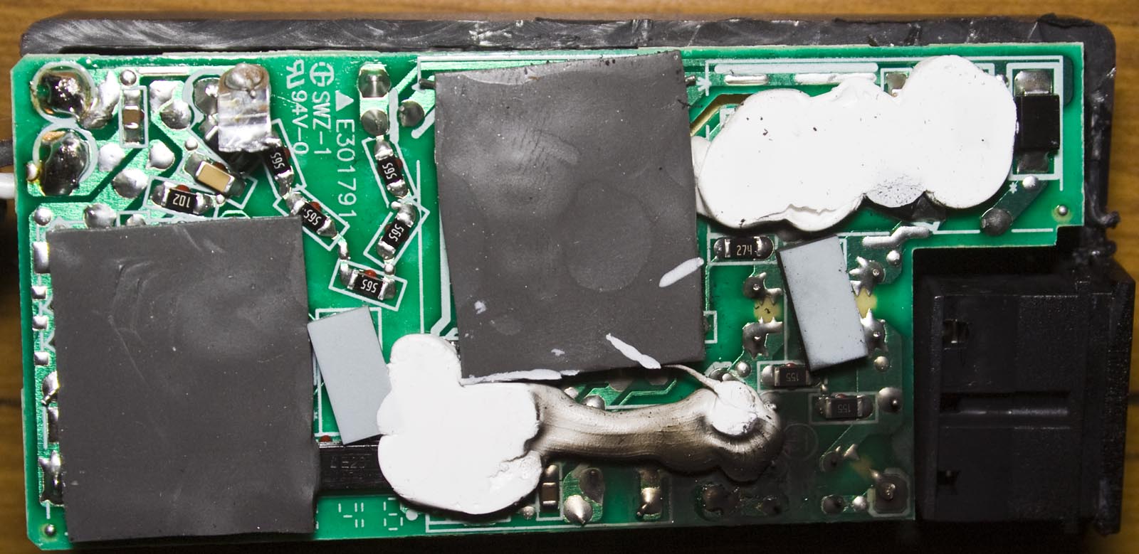
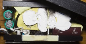
 Now we see lots of charring on the bottom of the board and most of it is pointing to around the front where the mains is connected near the fuse. Just above the black connector we have the diode rectifier, notice the resistor chain to the left and the PCB’s silkscreen has good markings where the pads, rubber or glue should go.
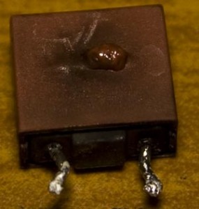
After desoldering the fuse, we can see that it’s blown pretty badly, it’s a 250V 3.15A. There must be some reason it’s blown or not?
(more…)
Read Full Post »
Posted in Teardowns on Oct 28th, 2014
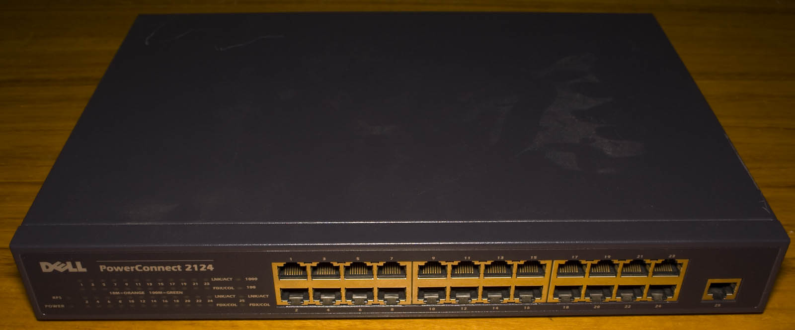
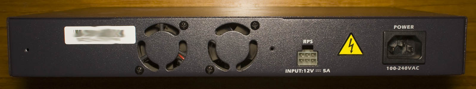
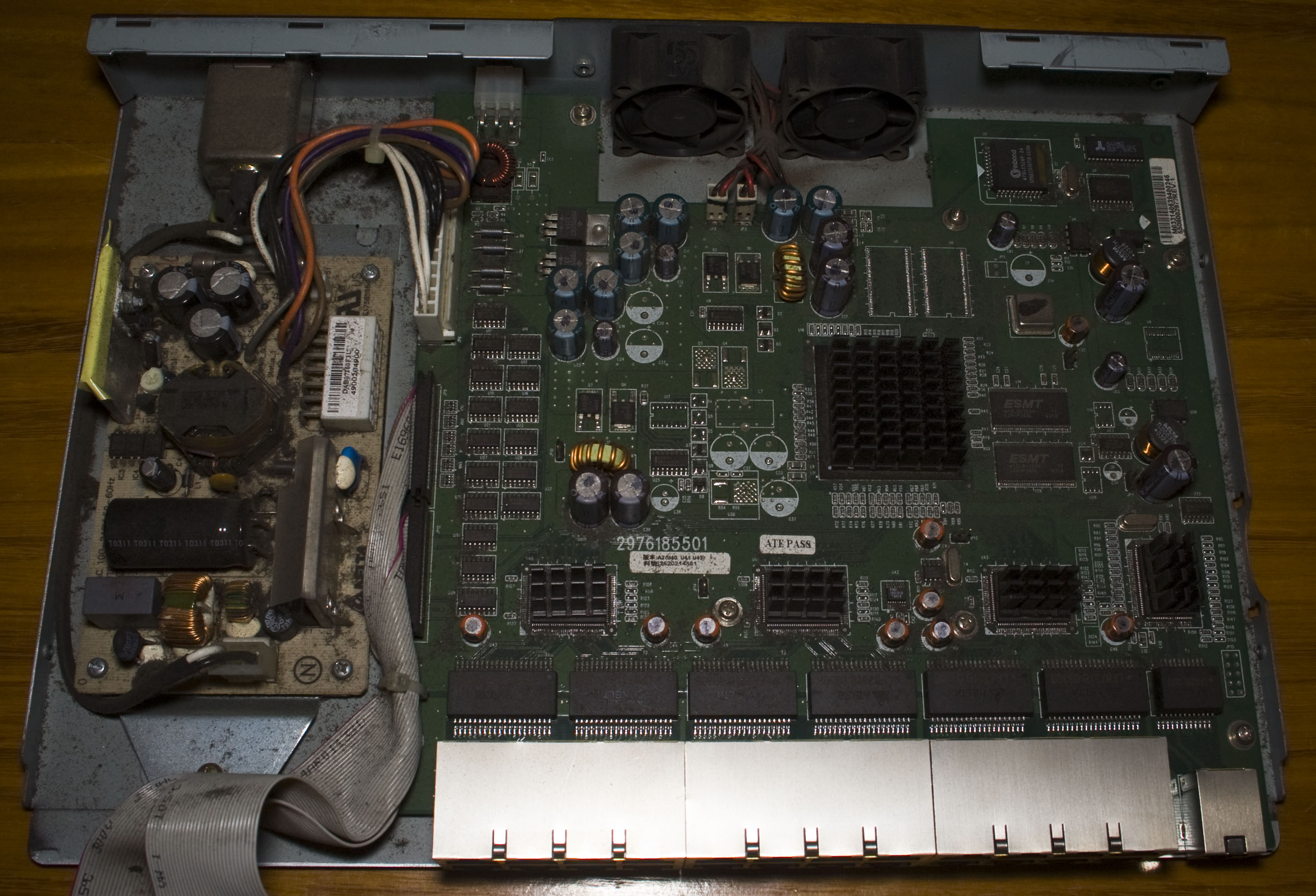
Today we’ll be taking a look at the Dell Power Connect 2124, a 24 Port 10/100 Switch with 1Gbit uplink. It’s got the capability of a redundant power supply and has 2 fans on the back, it’s a fairly old switch dated back to 2003.


A few screws later and we’re in.
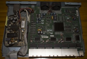
It’s a pretty dusty unit, we’ve got our power supply on the left which gives out 12V at 4.5A that connects to our main board and from the main board we have some cables running to the front panel. They’ve cut the board a little bit around fans to allow for better air flow.


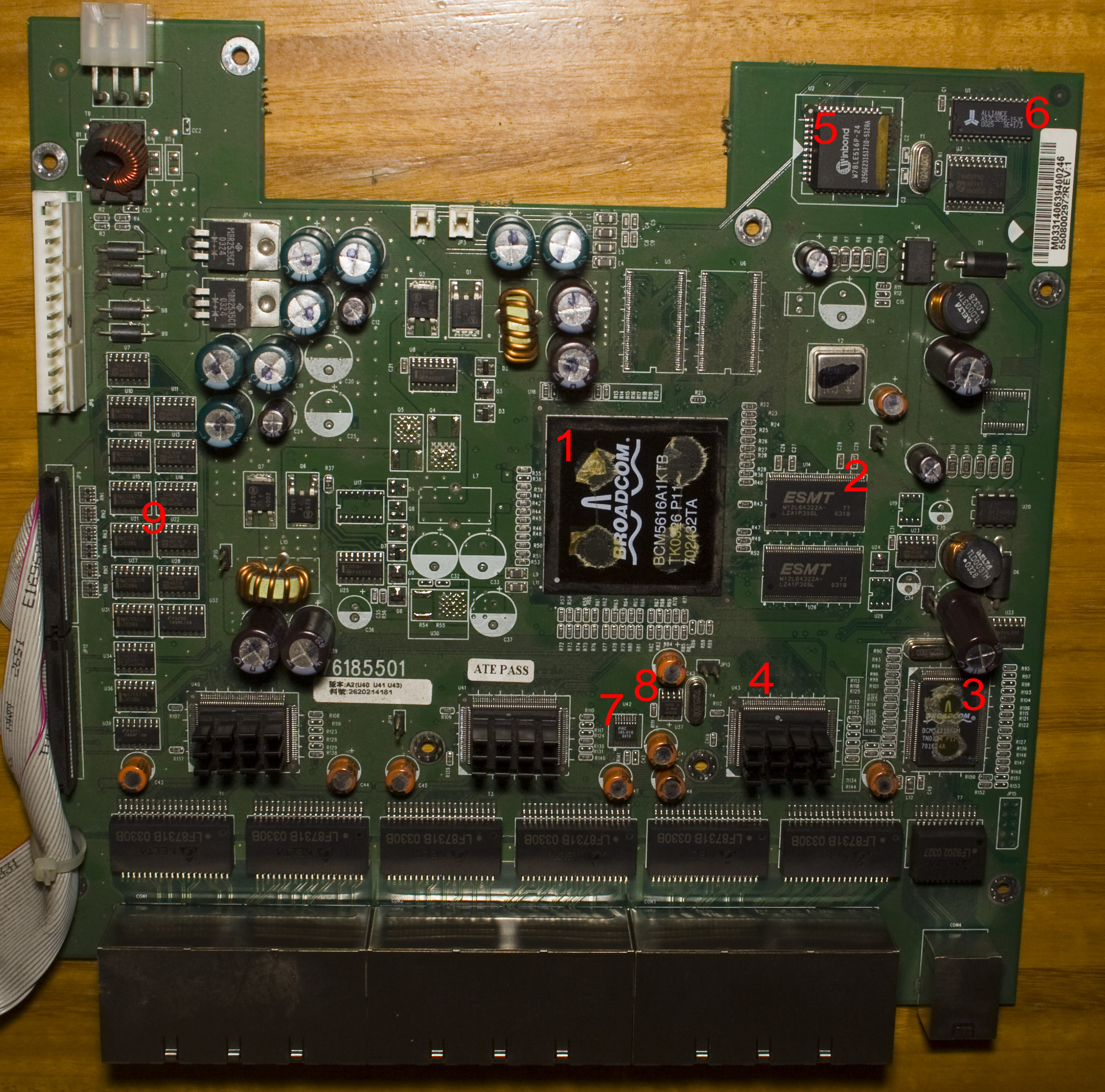
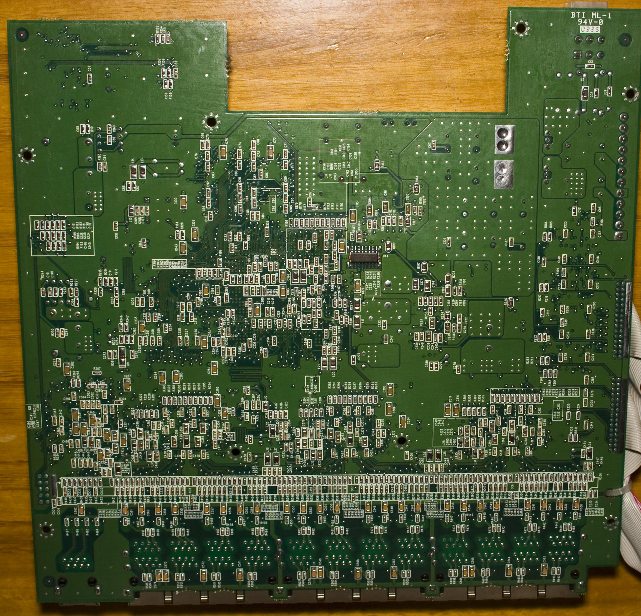
We’ve got a pretty large Broadcom chip in the middle that was under a heatsink – probably one of the largest I’ve ever seen and there’s heatsinks on each Broadcom PHY chip. If you look closely you can see the capacitor on the bottom right hasn’t been soldered down properly and the inductors nearby are a little like that too. There’s a whole heap of 74 series logic on the left which go off to the front panel. On the bottom we’ve got a fair few passives and a nice looking line of them too.
(more…)
Read Full Post »
Posted in Teardowns on Oct 13th, 2014
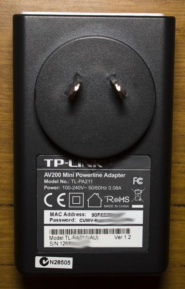
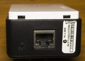
Today we’ll be taking a look at the TP-Link 200Mbps Mini Powerline Adapter (TL-PA211), an ethernet over power (EOP) device which won’t power up – this is the second one of these that has had power up issues.
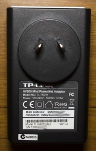
One screw later under the label and we’re in.

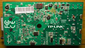

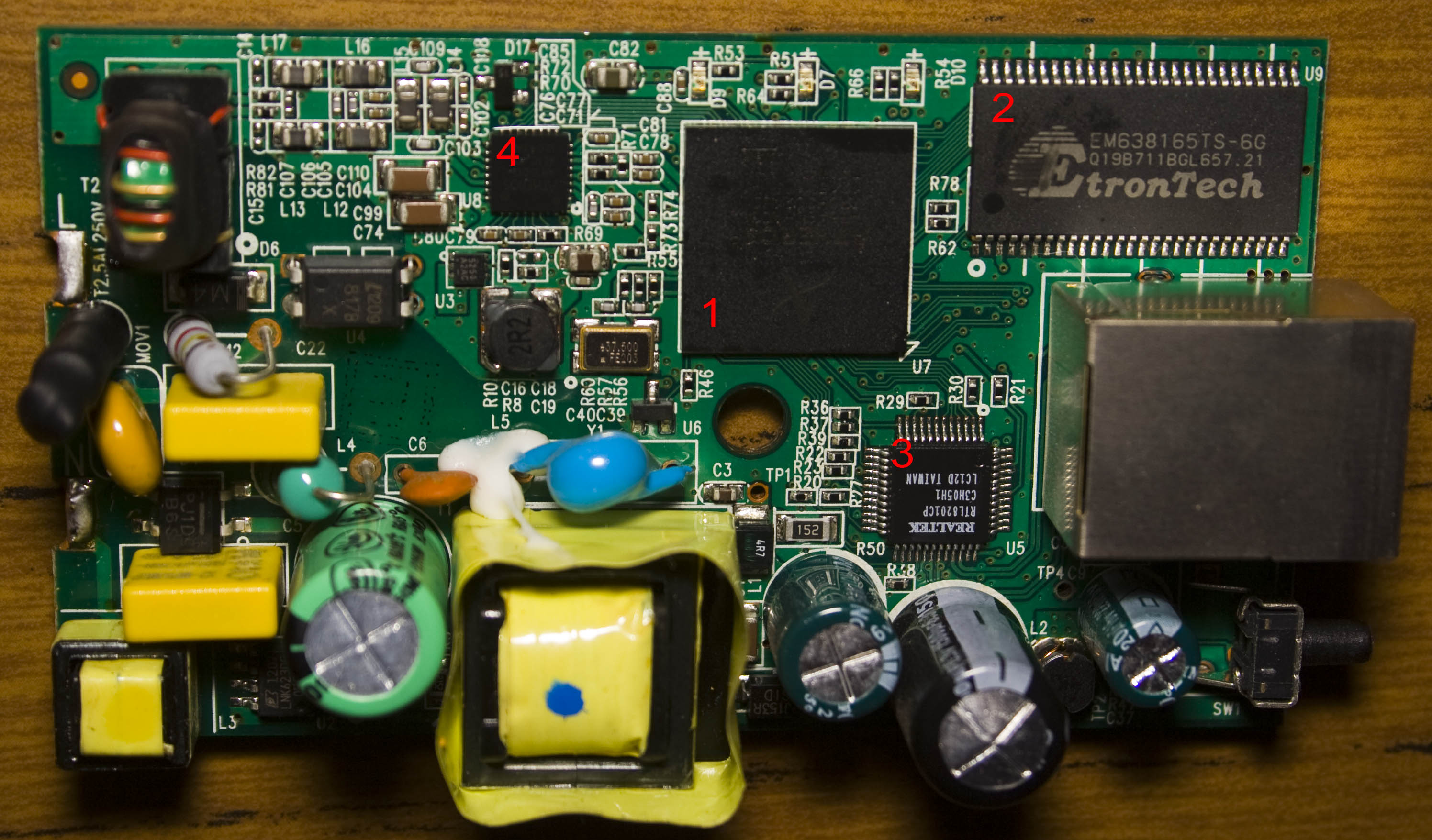
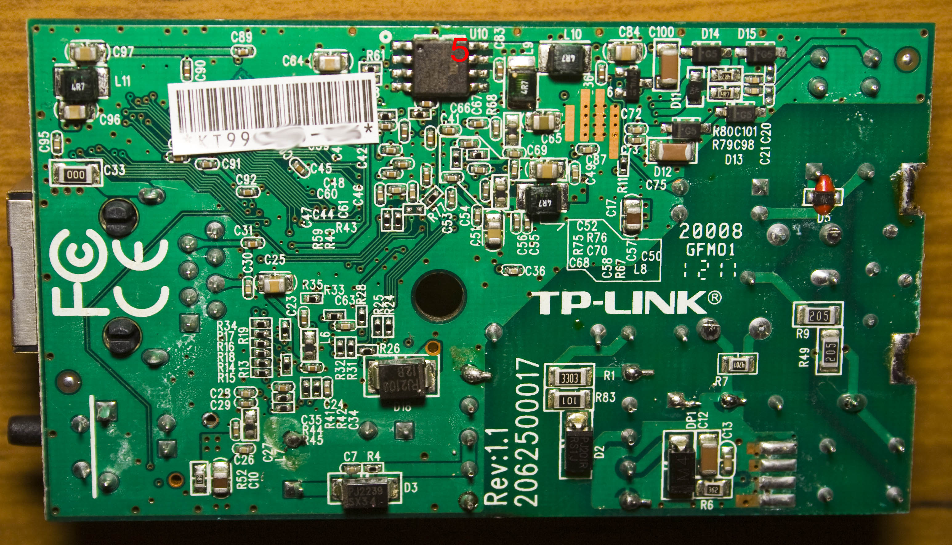
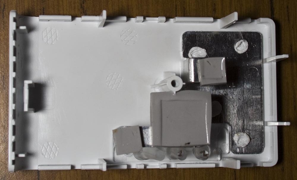
We’ve got the AC inputs on the left which are soldered on to the tabs, after unsoldering them the board pops out. There are a few heatpads on the top cover and the date code is 2012/11th week.
For the input power side of things we’ve got a Power Integrations LNK623DG AC to DC converter which can output up to 6.5W and this IC eliminates the need for an opto-isolator.
(more…)
Read Full Post »
Posted in Teardowns on Sep 28th, 2014
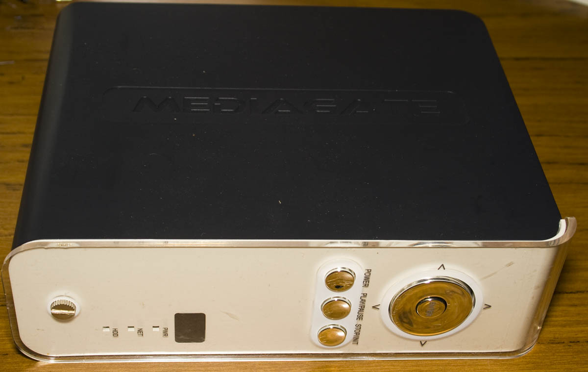
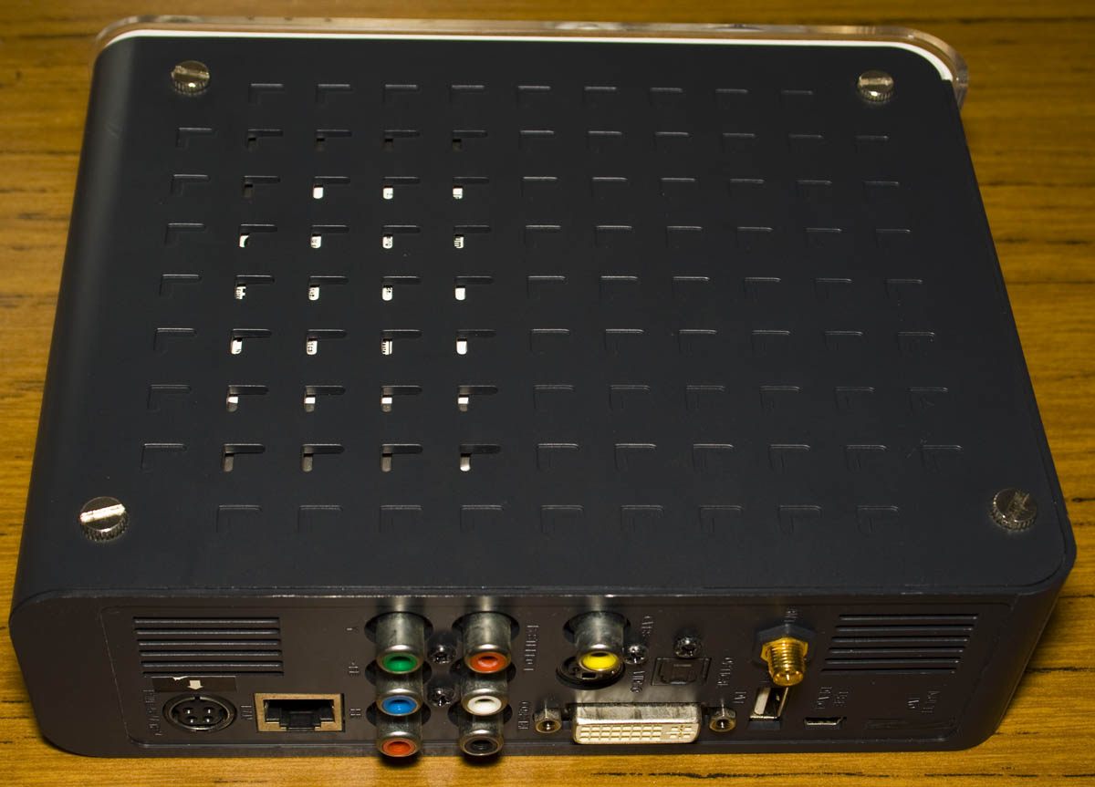
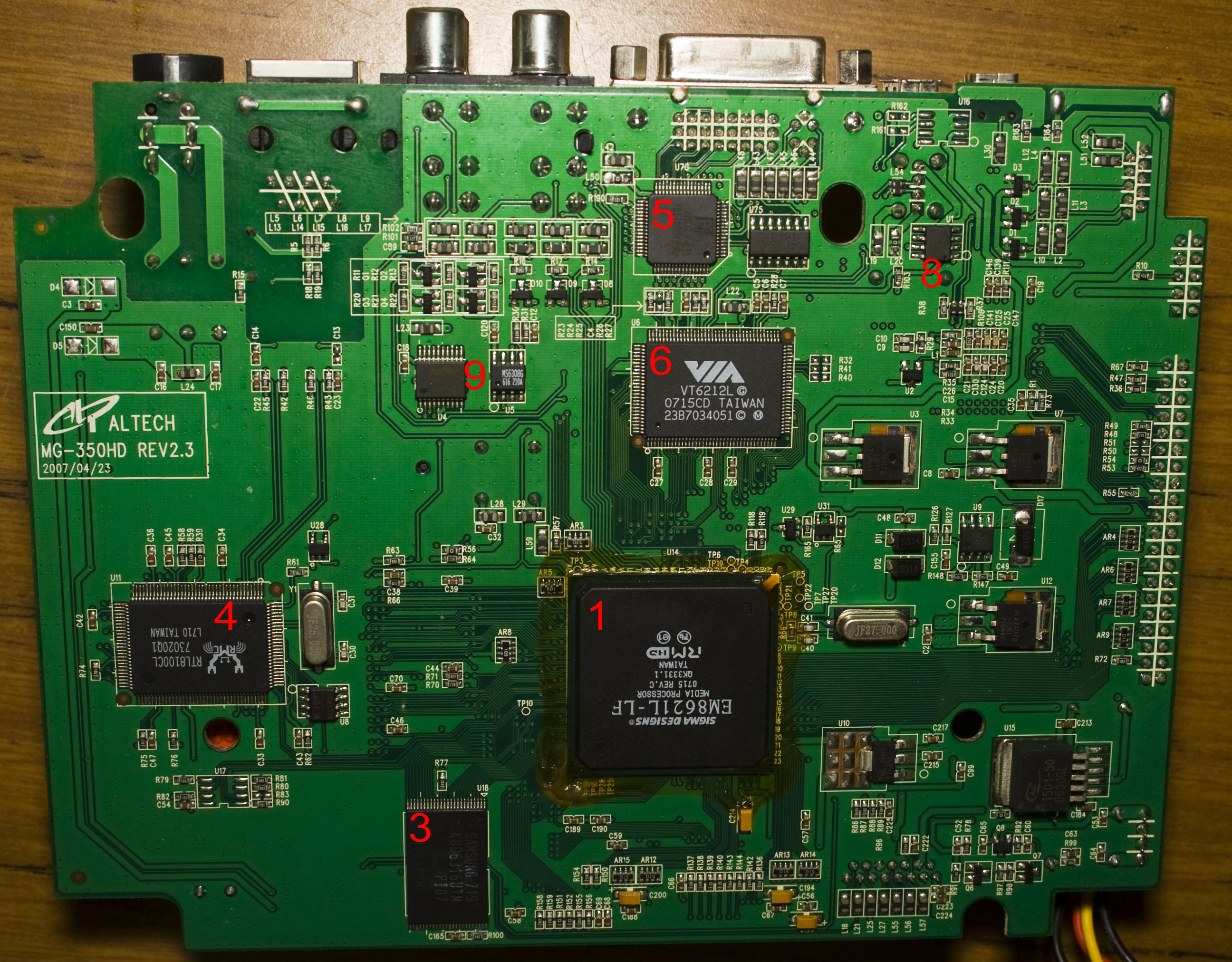
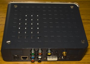
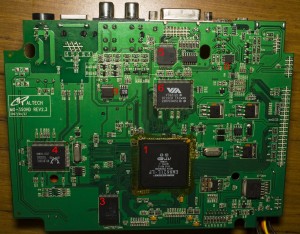
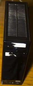
Today we’ll be taking a look at the MG-350HD Media Centre which is as it says, is a media center with Wifi/LAN, a 3.5″ IDE hard drive, USB with lots of outputs including component/composite/DVI/audio/optical so it’s pretty packed.

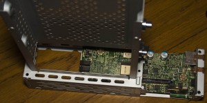
At first I wondered why it was so heavy, after opening it up there is a 750GB 3.5″ hard drive – so that’s why, it’s an IDE drive.
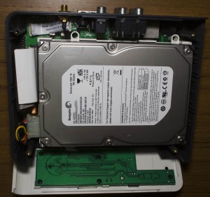
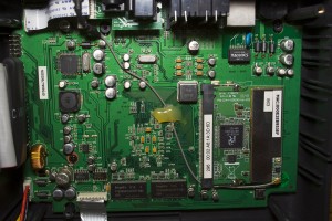
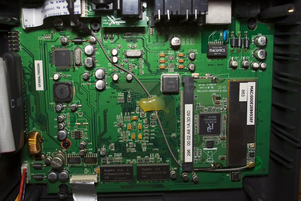
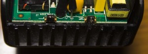
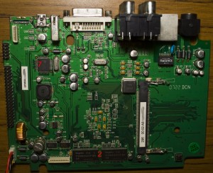
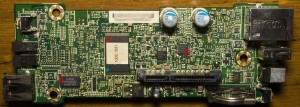
A few screws later and one screw under the wireless card, we’re in. We’ve got a fair amount of passives on the top with our Mini-PCI wireless card and on the bottom we’ve got chips with some regulators – 3x AZ1117 LDOs, 2x AP1605 SMPS and AP1501 SMPS. There’s flat flex cable connecting the optical/S-video and the front panel. PCB date code is 22nd week of 2007.
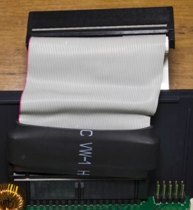
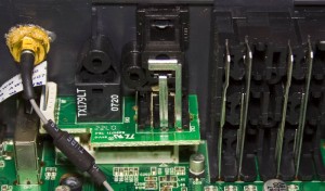
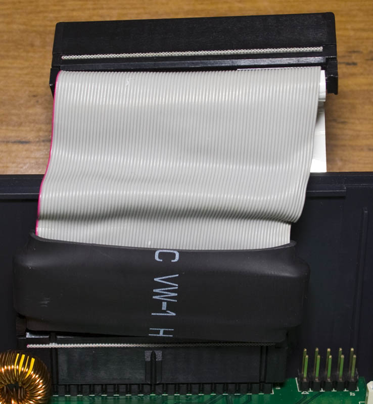
For the IDE cable, it looks like they have an ferrite core in heat shrink for EMI and it could be the same thing they are doing on the wireless antenna cable too. It’s interesting to see the video from the PCB to the connectors, the connecting conductors are pretty large.
(more…)
Read Full Post »
Posted in Teardowns on Sep 3rd, 2014
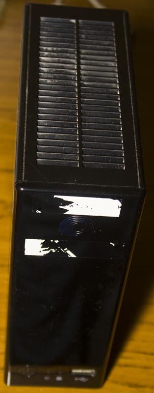
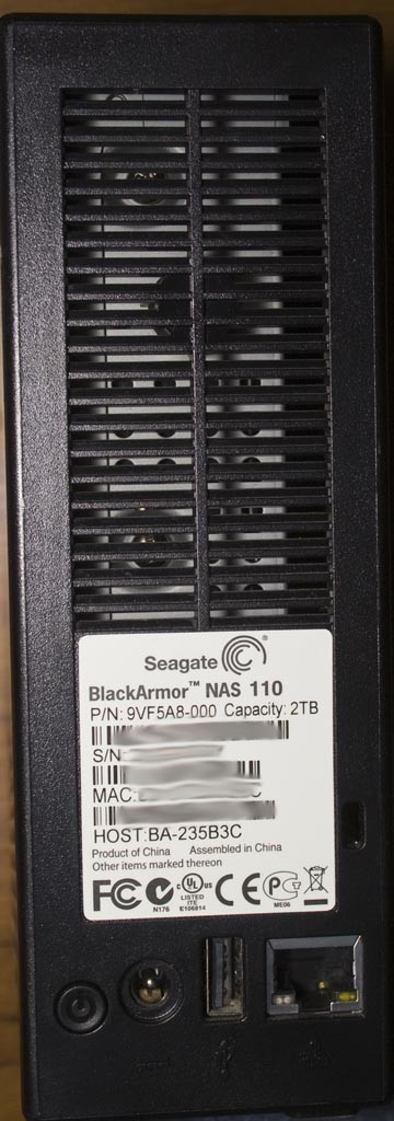
Today we’ll be taking a look at the Seagate BlackArmor NAS110 Network Attached Storage which has a single 3.5″ hard drive and 2x USB, it’s a pretty basic NAS. The date code is 2010/10th week.

Once the case comes off, you take the hard drive out and then slide out the PCB.
The top side of board looks like it has a lot going on but it’s more just all the part labels that make it seem that way.
We’ve got a 3V coin cell for a RTC, 2x chips most likely to be SMPS with a mosfet chip labelled 4468 BA012X / 4712 BV0226 as they are near the inductors, an APL1085 3.3V / adjustable 3A LDO and an APL5930 3A LDO. Something small that stood out to me was an SMD LED which emits its light horizontally instead of vertically.
(more…)
Read Full Post »
Posted in Teardowns on Aug 26th, 2014
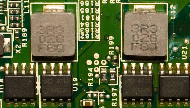
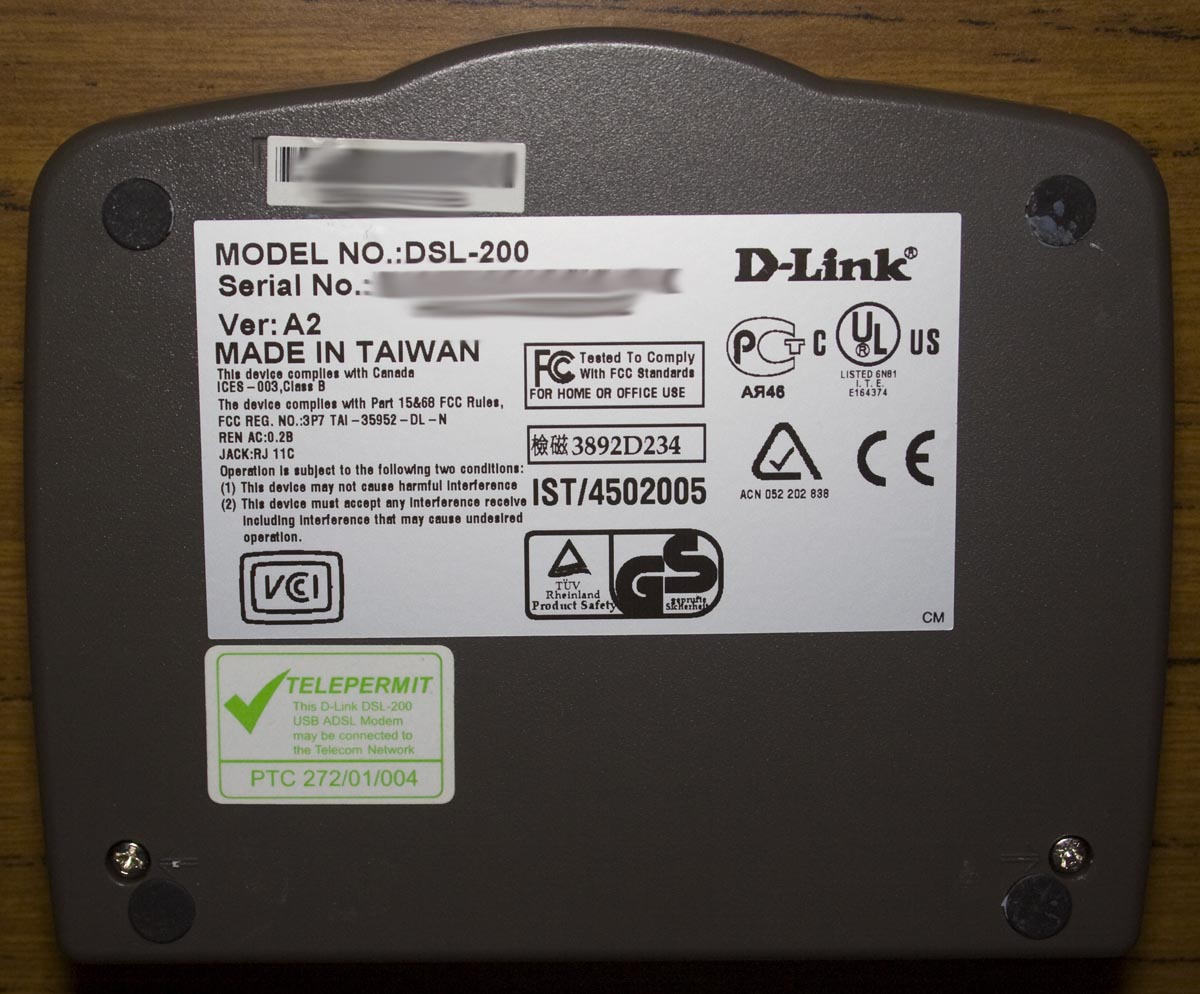
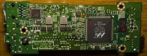
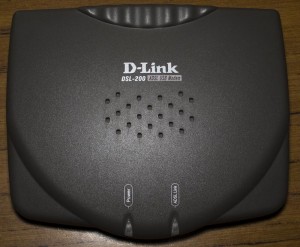
Today we’ll be taking a look at the D-Link DSL-200 ADSL USB Modem device which is the first ADSL modem I had back when we got ADSL in 2002, it’s a USB powered modem. The date code is 2002/27th week.

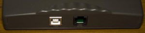
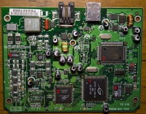
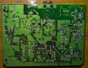
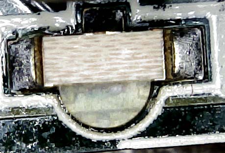
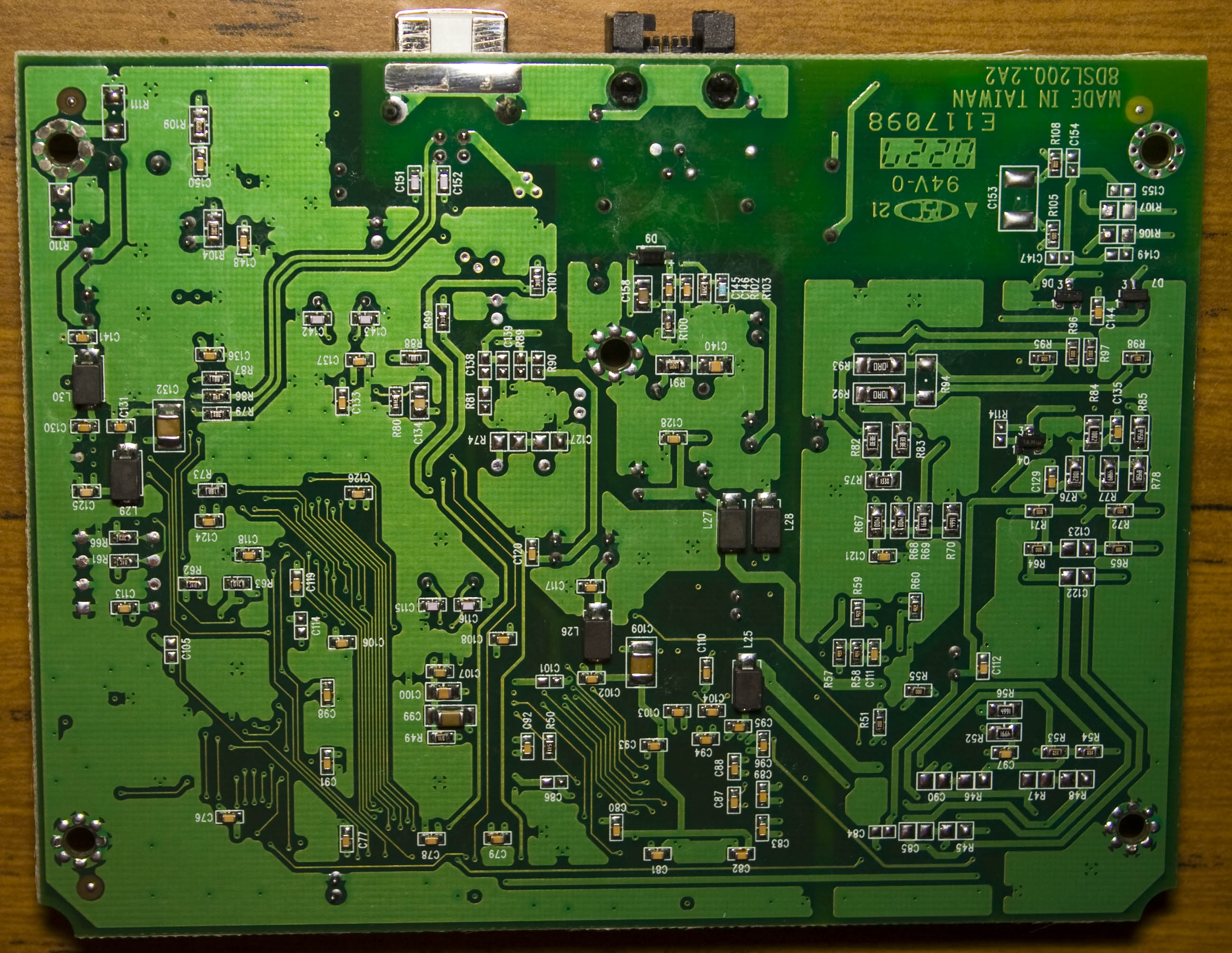
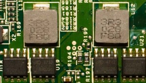
The top and bottom board have quite a bit of inductors, the top right side of the board has quite a few capacitor all bunched together and we’ve got a fair amount of chips. We have a On Semi 51031 SMPS with a IRF7416 P mosfet to form part of the SMPS and there’s a 5171E boost regulator likely to be for the ADSL side (in the middle of the board).
(more…)
Read Full Post »
Posted in Teardowns, Tinkering on Aug 14th, 2014
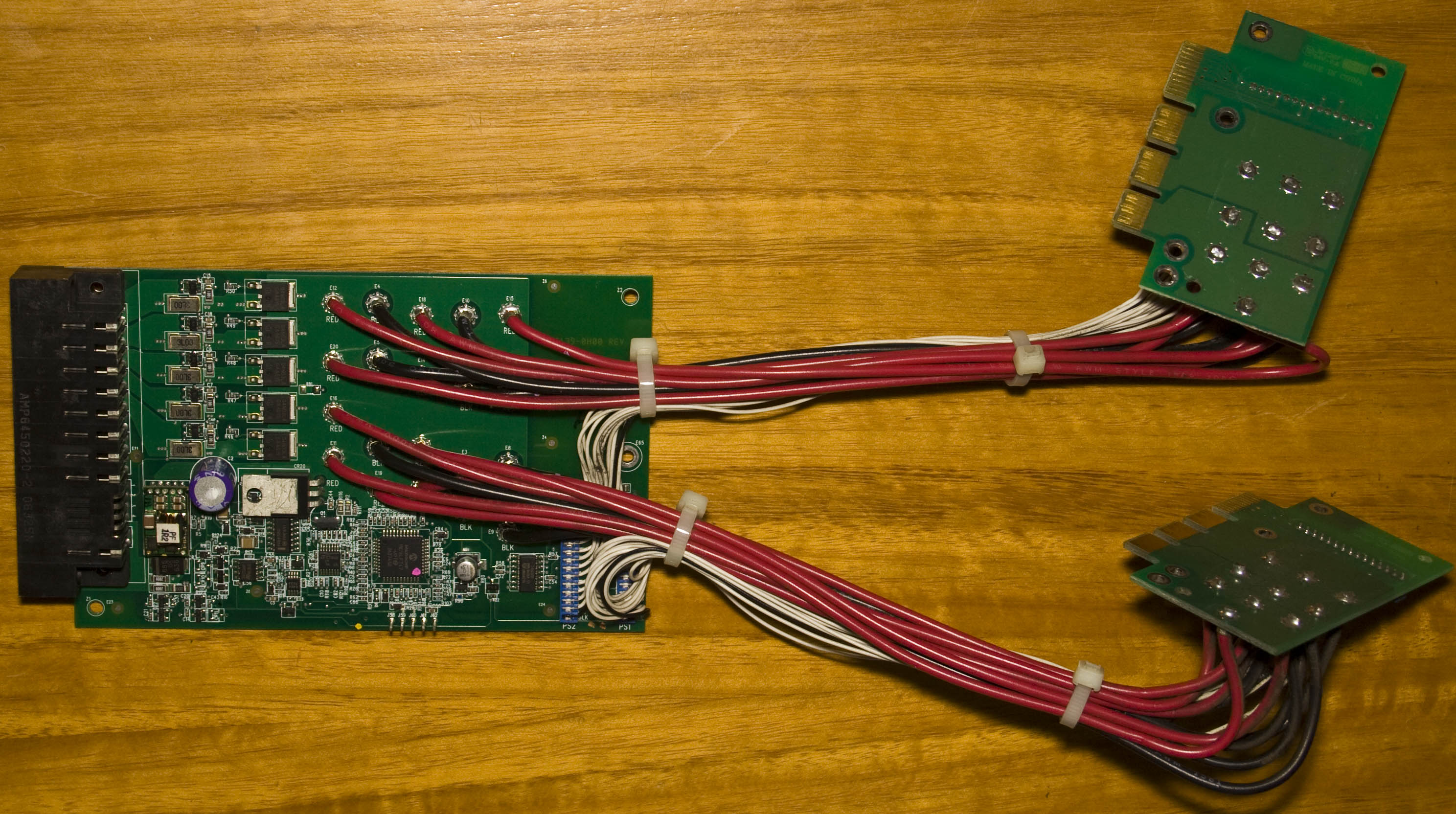
Today we’ll be taking a look at the IBM Server Redundant Power System (2006) board which was taken out of an IBM server, its purpose is to combine both power supplies into one and know when a power supply goes offline/online. The date code is 2006/46th week.

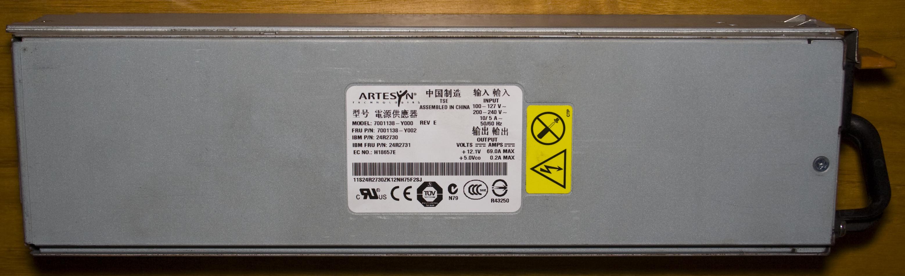
I was able to take both power supplies from the server which were rated at 12V at 69A which gives 828 watts which is unusual to have that much amps on the 12V rail and I would like to use each one independently of this RPS board which we’ll also look at.
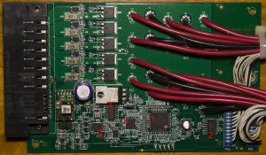
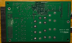
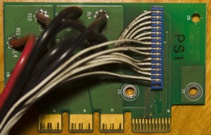
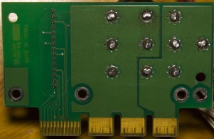
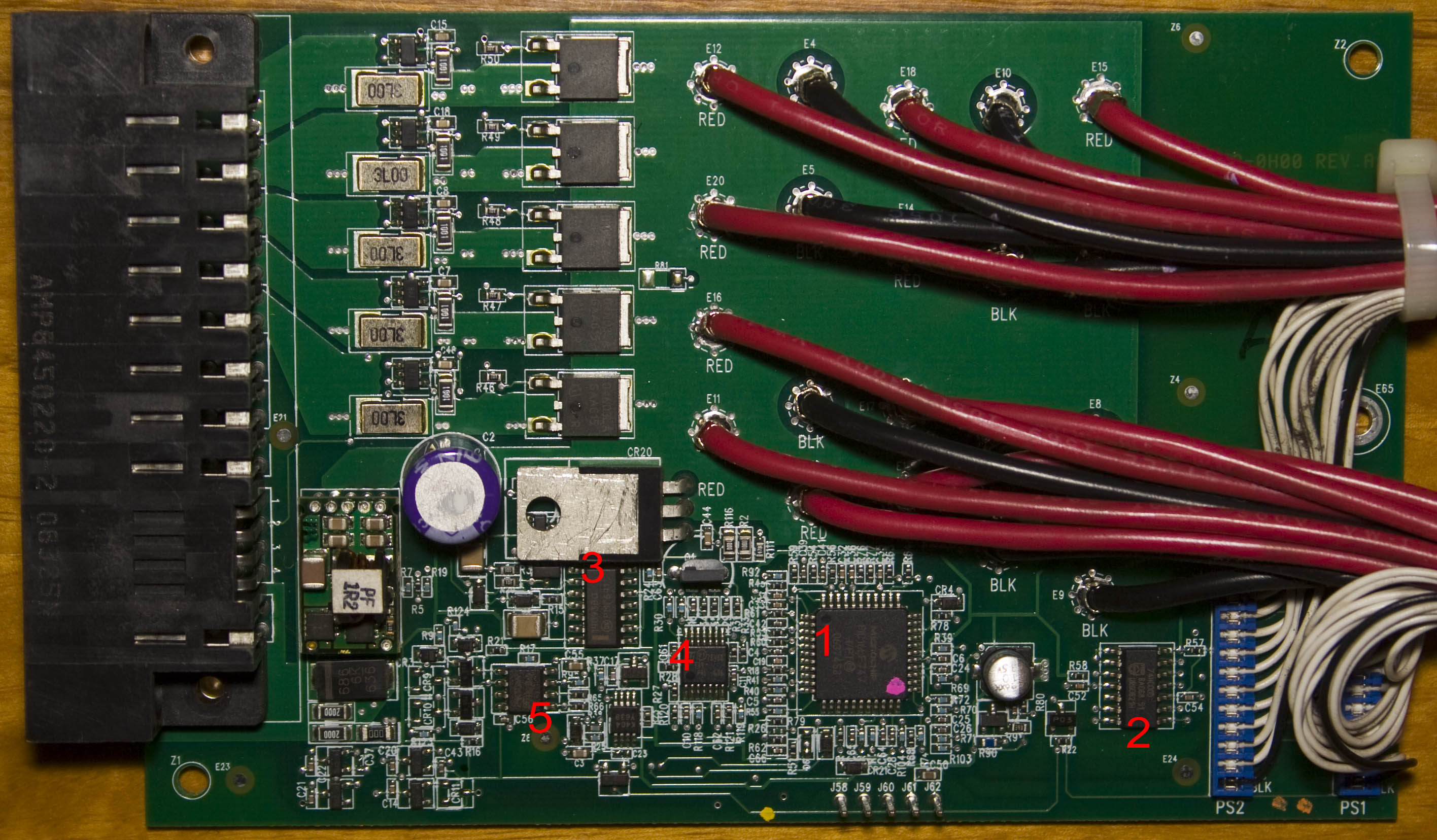
It’s a nice looking board and there are two sub-boards for the power supplies, all that’s being carried over is 12V on the thick red wires and some control lines too. We’ve got a little sub-board soldered on the main board too with two chips, some capacitors and an inductor, likely to be a SMPS. Another component that stands out is the TO220 part tipped horizontally to keep it low profile, usually you don’t see the metal part in the air like that. They’ve got a Infineon 04N03LA N power transistor and current sense resistor for the 5x 12V rails to regulate how much current each rail receives.
(more…)
Read Full Post »
Posted in Teardowns on Aug 7th, 2014
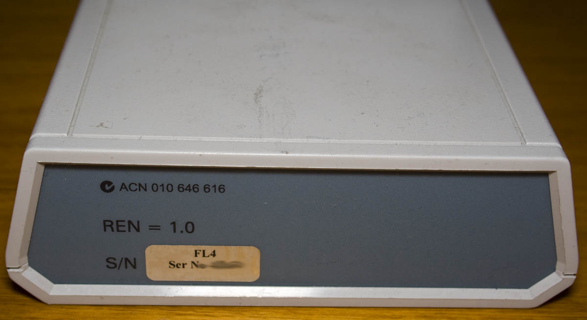
Today we’ll be taking a look at the Softlog Systems Faxlog 4 device which as it says converts incoming faxes to serial and then there’s another box which plugs into the PC. The date code is 2006/34th week.
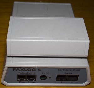
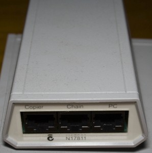

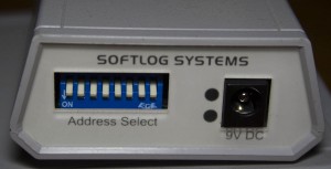
There was a RJ45 cable connecting this sub-board to the main board, whether or not this was all the parts in the Faxlog system is unknown. There is also a selectable address line via DIP switches.
Main Board
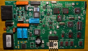

The PCB has a lot more ICs and components than I had expected. We’ve got some phone line filtering and protection with some larger than normal capacitors (compared to internet routers), along with 2 TIP31CG NPN transistors, some RY5W-K relays, a NMV0515SC DC-DC converter 5V input to 15V output and some P2769 / 100SMD transformers. Coming from the transformers / opto-isolators, we’ve got 3 UA741 opamps and 2 DG419 analog switches. In terms of power supply side, it’s 9V input with a large 1000uF capacitor, LM2940CT 5V LDO with heatsink and a NMA0505DC 5V input to -5 and +5V output.
(more…)
Read Full Post »