Posted in Arduino, Projects on Mar 16th, 2013
It’s been nearly 2 years since I last worked on my Gameboy Cartridge Reader (GBCartRead) and I never released a PCB but it has been something I’ve been meaning to do for a while which I can now check off my list.
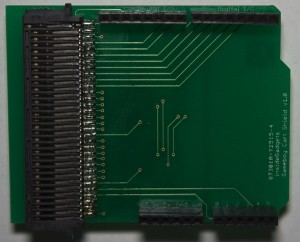
I received the PCBs for the Gameboy Cart Shield a few days ago, soldered all the components and noticed that somewhere along the lines I didn’t connect up the VCCs together so I have a bodge wire on the bottom of the board. Something I should have done was make the silkscreen text much larger than what it current is.
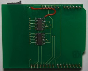
The Gameboy Cart Shield PCB is now available for sale.
Read Full Post »
Posted in Projects on Mar 9th, 2013
The PIR PCBs have arrived to be used on my alarm system.
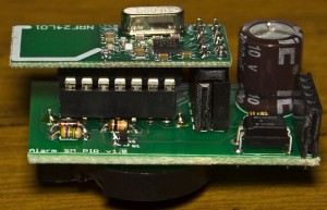
It all fits in nicely, with the nRF24L01 on top of the ATtiny and the 3V battery holder on the bottom.
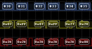
After testing 4 PIR boards at a time it seemed to work however after a few days of testing there seemed to be a board which would fail to connect. I connected up my logic analyser to a working PIR board and then to the one that wasn’t working after some time and below is the capture after it loads the random data to transmit.
Working PIR
Not working PIR
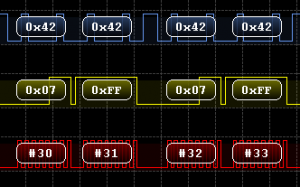
As you can see both request the status by sending 0x07 however the response is 0x2E vs 0x42 (Also notice how it sends us the reply on the same packet that we send the status request).
(more…)
Read Full Post »
Posted in Teardowns on Mar 3rd, 2013
Today we’ll be looking at the Belkin F7D4501 ScreenCast TV Adapter which allows you to transmit your laptop’s screen to your TV, the downside is it only supports laptops that have Intel’s WiDi. I don’t have a laptop that supports this, so only thing we can do is take it apart!
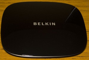
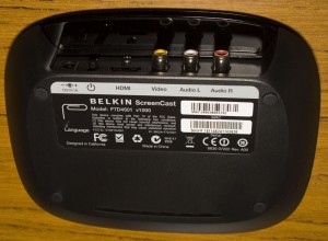
4 screws later and we’re in.
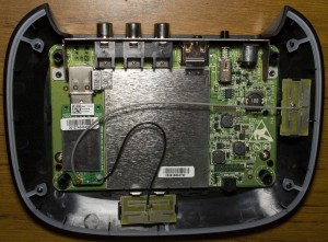
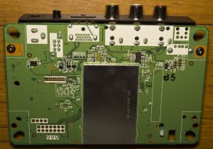
We have shielding on the front and back, 2 antennas and it appears there is a USB wireless dongle that’s plugged in which connects to the board – not something I was expecting to see. I plugged in the USB dongle to my computer and seems to be detected as a 802.11n WLAN.
(more…)
Read Full Post »
Posted in Projects on Feb 24th, 2013
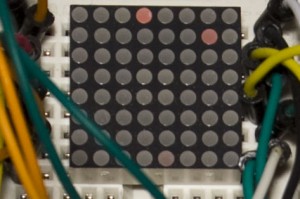
A while ago I picked up a small 20mm 8×8 LED matrix (LEDM88SMR) and have been thinking about making it battery powered to display some animations or text on specific dates such as on new years eve or on a birthday. I’m thinking of placing all the components on the underside of it so it will have more height but to not exceed the 20mmx20mm width/length.
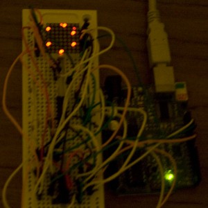
The first thing is to build the circuit up with the Arduino using 2x 74HC595s and since I’ve worked with LED Matrix’s before, I already have some code I can reuse. Now that it works, I thought I would start designing the PCB (a bit later on it will be re-designed). Download 8x8_LED_Animation for the Arduino.
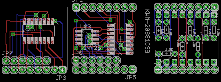
What I like to do first is lay out all the components and then draw in draft wires as place holders to make sure there won’t be any overlapping wires. I came up with 3 PCBs (left is bottom board, right is top board) which mount on each other using the Arduino style headers plus 1 more PCB for the battery. This design has an ATtiny25/45/85, 2 shift registers and 1.5K resistors.
(more…)
Read Full Post »
Posted in Tinkering on Feb 18th, 2013
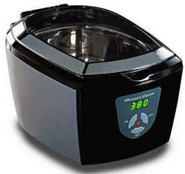
I was given a Visage Ultrasonic Cleaner to see if I could extend it’s timer settings from the maximum setting of 480 seconds to 960 seconds. An Ultrasonic Cleaner uses ultrasound to create small bubbles in the water and when those bubbles collapse it generates enough temperature and pressure to remove dirt and clean objects.
My first thought was that it would have a single board and that I would have to use an ATtiny to press the buttons in a sequence to turn it on for 480 seconds two times in a row. When I went to turn on the Ultrasonic Cleaner to make sure it was operational, it didn’t work. After shaking it a little bit, it seemed to turn on, so something is loose inside.
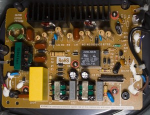
Upon opening it up, we have the single board but no MCU in sight. The components worth mentioning are the relay and 2 transistors (I assume they are due to the B / E marking) with heatsinks.
(more…)
Read Full Post »
Posted in Arduino, Tinkering on Feb 10th, 2013
Following on from my post on How to use Nokia F-bus to send an SMS message where I used an Arduino to send an SMS message, at the end I mentioned moving to an ATtiny2313A/4313 so that we don’t need to use the Arduino.

The ATtiny2313A/4313 features Universal Synchronous and Asynchronous serial Receiver and Transmitter (USART) with the features above. The Nokia F-bus uses 115,200 bps with 8 data bits, no parity bit and 1 stop bit.
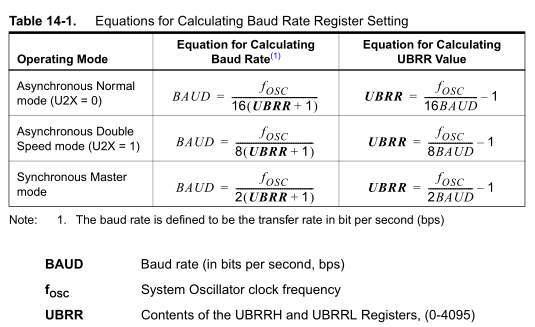
To use USART we need a clock input, there are 3 clock options – Asynchronous Normal, Asynchronous Double and Synchronous Master. For Asynchronous, the clock is generated from the system oscillator where as the Synchronous option is where we provide an external clock signal input. Using the UBRR register we can dial into the baud rate that we want but it depends on the system oscillators frequency.
(more…)
Read Full Post »
Posted in Projects on Feb 3rd, 2013
So the Standalone Temperature/Voltage Logger has worked out but I wanted to make a temperature logger more smaller and in doing so, switch back to the two board idea I originally used – one be the logger and the other be the reader.
It appears that most people who have bought the SATVL go with the 512Kbit EEPROM so we’ll provide that EEPROM as the only option and use 2 bytes per reading. In wanting to make everything smaller, it’s time for us to switch to SMD parts.
The most important part is which ATtiny MCU to go with. I was thinking of the ATtiny10, a very small chip but it only has an 8 bit ADC. The next MCU I thought of was the ATtiny13 but I found that the cost of it was more than an ATtiny25, so the ATtiny25 it is.
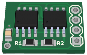
(sneak peek of PCB)
.
Logger Schematic
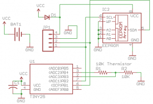
The logger board will be very simplistic, just a 10K thermistor, 10K resistor, 0.1uF capacitor, diode, battery and 4 pin header which breaks out VCC, GND, SDA and SCL. When we want to extract the data, we need to remove the battery and connect the 4 pin header to the reader which directly connects to the EEPROM. The reason the diode is there is so the ATtiny25 doesn’t power up and start re-logging.
(more…)
Read Full Post »
Posted in Teardowns on Jan 25th, 2013
Today we’ll be looking an Alcatel Lucent 9361 Home Cell V2 which is used as a small base station to provide your mobile phone with better reception.
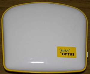
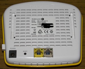
A few notches later and we’re in, no screws needed to be removed but it was a bit of a pain to get in.
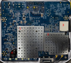
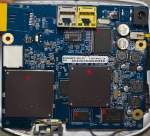
When you pick up the board it’s a bit heavy compared to other PCBs and straight up we can see 2 metal covers which is what you’d see in mobile phones. There is also a plastic cover as well which is a little strange. On the back of the board we can see that we have some metal blocks and an unpopulated section at the top left, maybe for a micro SD card slot?
(more…)
Read Full Post »
Posted in Projects on Jan 20th, 2013
I’ve decided to come back to this project after learning how to use the ATtiny’s ADC in differential mode. With the ATtiny44A we can use a gain of 20x for the differential mode and if we used a 1 ohm resistor with a load of 100uA, it would give us reading of 2mV (0.1mV x 20) which means we could remove the op-amp from our circuit.
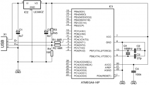
I also wanted to remove all the level shifters from the circuit and have it all powered by the USB instead of using a battery. There was an example of a V-USB circuit which used a 3.3V low voltage dropout regulator and I was able to get my hands on an LP2950.
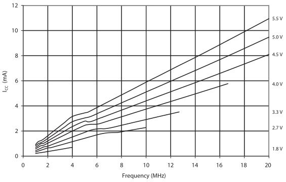
Since we will be running the ATtiny44A at 3.3V it can’t run at 16MHz but it can run at 12MHz and V-USB supports this too (if we didn’t get the ATtiny44 “A” version then 12MHz at 3.3V isn’t supported).
(more…)
Read Full Post »
Posted in Arduino, Tinkering on Jan 12th, 2013
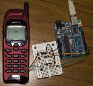
A few months ago I was looking into how to use Fbus with a Nokia phone but didn’t have much luck and instead just wired up the keypad. I decided to revisit Fbus and this time happened to find some AVR code which could send/receive SMS’s so now I’m able to send an SMS using the Arduino and I’ll explain how we do this.
Before I go any further the 3 resources I used were:
Embedtronics – F-bus packet explanation with some examples of a packet
Avr and nokia3310 interface(sms) project on AVRfreaks – Code for an AVR to send/receive SMS
Gnokii – F-bus documentation and code to run on a computer
Firstly you need a Nokia phone which the F-bus commands are known, the best documentation is available for the Nokia 6110 and derivatives (Nokia 6130, 6150, 6190, 5110, 5130, 5150, 5190, 3210, 3310) – this was found in \gnokii-0.6.31\Docs\protocol\nk6110.txt
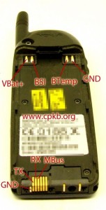
I was able to purchase a Nokia 6150 from Ebay for under $20. You can search up the Nokia pinout for your mobile phone – I found the TX, RX and GND for my phone.
(more…)
Read Full Post »


