Posted in Projects on Oct 11th, 2012
The Standalone Temperature/Voltage Logger has now been updated to v1.2 – download here and is now back in stock with the v1.1 PCB now available which fixes the Q3 Mosfet issue with the v1.0 PCBs.
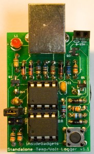
The v1.2 update fixes a bug where the calibrateOscillator function wasn’t been called when USB was plugged in so only a few ATtiny’s would work. Also instead of using delay whilst waiting for the ADC result we now use the ADC noise reduction sleep mode which should give just that tiny bit more accuracy and also saves a little bit of power.
Read Full Post »
Posted in Miscellaneous on Oct 5th, 2012
About 1-2 weeks ago I bought a cheap power adapter with an output as a USB connector from Ebay which says it does 5V @ 1000mA. I would be drawing about 500mA – 700mA from it.

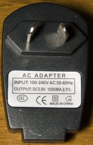
I’ve heard about bad stories about cheap power adapters (the “one hung low” kind) and straight away measured the voltage output and it did seem to be at 5V. I used the USB cable provided which I found to be terrible – it had a voltage drop of 2V – threw it out straight away.
For a few days the adapter seemed to work – then all of a sudden I heard a pop.
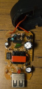
It looks like the resistor had fried and lost it’s connection.
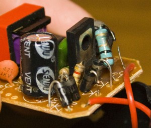
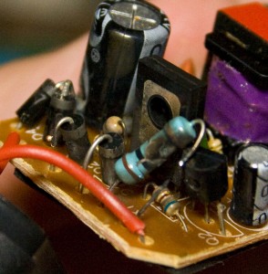
On closer inspection, a diode lost it’s connection too.
I’m now using an Apple charger which is rated at 2A so I should be good now.
Read Full Post »
Posted in Projects on Sep 29th, 2012
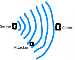
Following on from Part 2, we looked at two way communication between the PIRs and the alarm system. In this part we’ll look at how we can secure the communication otherwise potential attackers could listen to the messages and control our PIRs. This part might be a little over the top for your typical project (e.g a logging project) but for my alarm system I think it’s worth going into.
Finding a solution
As anyone who knows a little bit about security, designing your own security protocol is a bad idea which I knew from the start but still wanted to give it a try. One problem we have is that the server only has 2 alarm states to send to the client, either turn on or turn off.
(more…)
Read Full Post »
Posted in Projects on Sep 20th, 2012
Following on from Part 1, we defined the modifications to make to the existing alarm system. In this part we’ll look into the two way communication for the PIR sensors, to be able to turn them on/off wirelessly.
We learned how to use the nRF24L01 module in one way communicate mode so we’ll need to modify that to have two way communication so that the PIR sensor can check in with the alarm system and receive a response back. I have 5 PIR sensors which I’m looking to do this for so the alarm system will need to listen for each one. From here on in I’ll refer to the PIR as the client and the alarm system as the server.
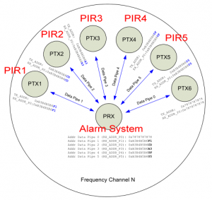
By looking at the datasheet it shows a configuration with one receiver communicating with 6 other transmitters at once. The nRF24L01 has 6 data pipes and when ever a packet arrives, we can check which data pipe it came from. This is useful because we may be in the middle of talking to PIR1 when PIR2 sends a packet, we wouldn’t know it was PIR2 if we don’t check the data pipe. If this happened, we would want to ignore PIR2’s packet and have it retry again later but in my example we only do one receive and one transmit so it doesn’t matter in my case.
(more…)
Read Full Post »
Posted in Tinkering on Sep 10th, 2012
Following on from my post outlining the modifications I wanted to make to my alarm system, it seems that one of the PIR sensors has started to play up. I tested the 9V battery which was flat and reading 6V or so.
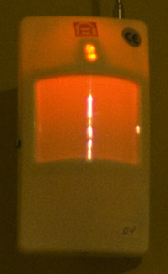
After replacing the battery, it still seemed to have some problems – when it detected movement, it would keep thinking it detected movement and switching the LED on and off every 4 seconds for about a minute or so (or maybe even longer).
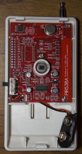
Above is the picture of the PCB for reference. I started measuring voltages and compared it to another PIR sensor but there wasn’t a difference in voltage that stood out.
(more…)
Read Full Post »
Posted in Projects on Sep 8th, 2012
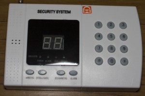
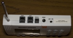
I picked up a cheap alarm system from Ebay (the “99zone” alarm) which came with a few wireless IR sensors and magnetic sensors that run off batteries and it all seems to work well and I’m looking to add more functionality to it.

The IR sensors have a switch to turn them on or off and are powered by a 9V battery. The only problem is that this switch is more of an inconvenience as you have to walk around to each sensor to turn them on or off. You could leave them always on but eventually the battery will run out in maybe a few weeks/months – the batteries were supplied with the alarm system so they might be pretty cheap batteries. When the IR is activated, it draws about 8mA for 2 seconds.
(more…)
Read Full Post »
Posted in Projects on Sep 2nd, 2012
I received the PCBs for my ATtiny Programmer Adapter v1.1.
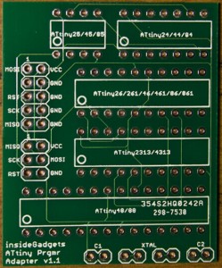
Built it up and it works well, I’m happy with it. The ISP connector is a tight fit, if I made the 6 pin / 10 pin ISP connectors any closer the connector wouldn’t fit. Tested all slots except the ATtiny48/88 slot as I don’t have one of those MCUs.
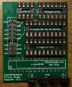
Should have probably added an LED to show there is power to the board. Need to buy some machine pins to make it easier to insert/remove the chips.
Read Full Post »
Posted in Tinkering on Aug 22nd, 2012
I decided it was time for me to play around with wireless communication as I recently purchased a wireless alarm system. I was able to pick up two nRF24L01 wireless modules very cheaply at about $2 each from Ebay.

Some features of this chip are:
- 126 channels
- Up to 32 bytes payload data
- Up to 2Mbps
- About 12mA current consumption when receiving or transmitting
I found there is a RF24 library for the Arduino and a similar library for the AVR. However after looking through nRF24L01 datasheet it appears that the AVR library version appeared a tiny bit incomplete so I’ve made some changes to the code.

The nRF24L01 modules uses 6 data pins but you can get by with only using 5. There are 4 for the SPI, 1 for the chip enable (CE) which sets the nRF24L01 in listen or transmit mode and an interrupt pin (IRQ) which can alert us when a packet arrives, packet is sent or maximum retries reached. I don’t use the interrupt pin in my example.
In my example, I have the transmitting code running on the ATtiny and the receiving code running on the Arduino so I could easily print the results. We run the nRF24L01 from the 3.3V pin on the Arduino.
(more…)
Read Full Post »
Posted in Projects on Aug 13th, 2012
The Standalone Temperature/Voltage Logger has now been updated to v1.1 which includes the v1.1 PCB to correct the errata that was on the v1.0 PCB. This new firmware version also introduces the satvltransfer program which allows you to transfer your data from the SATVL more quickly like the SACL v0.4 does. The benefit of this is that it doesn’t need to emulate your keyboard so you can keep using the computer when it’s transferring data.
Both the v1.1 and v1.0.1 firmware are included in the download file: Standalone_Temperature_Voltage_Logger_v1.1
If you have the SATVL v1.0 PCB/Firmware, all you need to do is program the ATtiny85 with the new v1.1 firmware. To use satvltransfer, plug in the SATVL to your computer, press the button as normal and then just double click the satvltransfer.exe file

It will generate a file name based on the current date and time and show you the data being transferred. For anyone not running Windows, the source code is available for you compile it to run on your operating system.
Read Full Post »
Posted in Teardowns on Aug 6th, 2012
Another quick teardown, this time we open up an Energizer AA/AAA/9V battery charger.


3 screws later and we’re in. At first it looks like a single layer board but on the back there’s a double sided board.
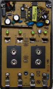
(more…)
Read Full Post »


