Posted in Projects on May 6th, 2012
Following from Part 3 we tested logging the op-amp’s output, storing the results in the ATtiny’s SRAM and transferring it to the PC. Now we’ll use external SRAM instead of using the ATtiny’s SRAM.

I’m using a Microchip 23K640 SRAM which has a voltage range of 2.7-3.6V. It looks like with SRAM there aren’t many around that can do 2.7-5.5V, this means we won’t be able to power the SRAM from the USB directly when transferring data, we’ll need to use a regulator and level shifters.
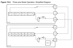
Before we integrate the external SRAM to our current schematic, we need to take a look at how to access it, it uses the SPI protocol. SPI is as simple as I2C except that instead of accessing a device by address, you pull the chip select line on the device low and instead of 2 wires you need 3 wires (plus one from chip select). Potentially you could have a lot of SPI devices on the same bus, you would just need a chip select line for each of them.
(more…)
Read Full Post »
Posted in Projects on Apr 28th, 2012
Following from Part 2 we configured our op-amp and tested to make sure it worked like we wanted it to. Now it’s time to test logging the op-amp’s output using the ATtiny’s ADC, storing the results in the ATtiny’s SRAM and transferring this to the PC.
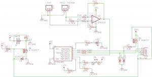
Here is the current schematic.
.
ADC Prescaler / Interrupt
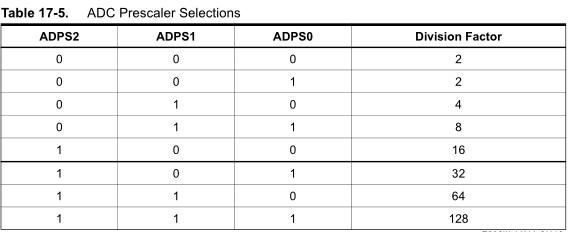
Before we continue, previously I based my assumption of the ADC conversion only taking 65us when at 200KHz however if we use the ATtiny’s internal oscillator for CPU clock speeds (1Mhz, 2Mhz, 4Mhz, etc) there is no ADC clock division / CPU clock combination that will give us 200KHz.
(more…)
Read Full Post »
Posted in Projects on Apr 18th, 2012
The Standalone Temperature/Voltage Logger v1.0 has now been released. Download SATVL v1.0 or view the Standalone Temperature/Voltage Logger project page. In the download, I’ve include a PDF guide file that has everything you need including step by step assembly instructions with pictures.
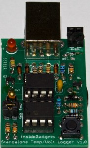
After about a months wait I’ve received 10 boards from Itleadstudio, they look good and I have successfully built a board up and it’s working. The SATVL is not currently up for sale at the moment until I receive a few more parts I’m expecting which should be in about 1-2 weeks.
During the testing process I found a few problems and a design flaw that made it to the PCB however it’s correctable and still functions as it should.
(more…)
Read Full Post »
Posted in Projects on Apr 9th, 2012
Following on from Part 1, we built our op-amp circuit and now it’s time to test it out. I ordered both the LM358 and OPA333 and began by testing the circuit on the LM358 as it was a DIP part.
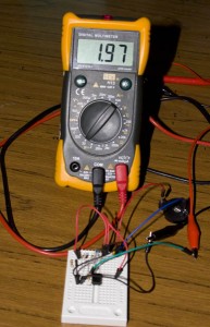
I was powering the circuit from a 3V battery and was seeing something very strange; the output was 1.97V with no load connected.
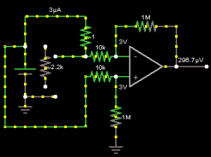
It didn’t seem to match the circuit diagram above.
(more…)
Read Full Post »
Posted in Miscellaneous on Mar 31st, 2012
I was given the chance by the kind folks at Element14 to select a part from their website and do a review on it. I chose the Olimexino STM32 board as it’s the next step up from the Arduino and can act similar to an Arduino. The Olimexino STM32 uses an ARM microprocessor running at 72MHz which is 4.5 times faster than the Arduino’s 16MHz. You can find the Olimexino range of products at http://au.element14.com/olimex/.
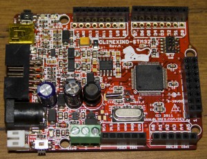
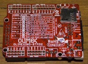
It has the following key features packed into the one board, to see more of the features click here.
– Allows 9V to 30V input
– microSD card capability
– Ability to use and recharge a Li-Ion battery
– ARM 32-bit processor with 128K flash, 20K SRAM, 12-bit ADC, 16-bit PWM, 39 I/O pins, SPI, i2C, CAN, RTC, etc
Note: The ARM micro doesn’t feature an EEPROM like AVR micros do.
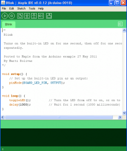
As the Olimexino STM32 is based on Maple (or seems to be) we can use the Maple’s IDE (which is a re-brand of the Arduino’s IDE) to start writing and uploading code with ease, most Arduino functions have been ported to the IDE. We have the blinking LED sketch shown below.
(more…)
Read Full Post »
Posted in Projects on Mar 23rd, 2012
In my Adding EEPROM to the SATL post I briefly spoke about my multimeter not being about to measure the current of the SATL when it was writing to the EEPROM, mostly due to the fact that it happens so quickly in under 50ms. I decided that solving this problem would be my next project to work on.

My thoughts are to have an MCU sampling the ADC, use a resistor’s voltage drop to calculate the current then write the result to SRAM (instead of an EEPROM as it would take 10ms for each write). If possible, I would like it to also be powered by a 3V battery.

The maximum ADC samples per second that the ATtiny85 can do is 15,384 (15KSPS) at 200KHz which when compared to chips designed specifically for ADC that run at 200KSPS doesn’t seem like a lot, but in our case it’s a lot. The reason is that if we had a 64Kbit SRAM, it would only be able to store 8,192 samples which is just over half of the 15K samples per second, it would only record 0.5 seconds before running out of space. For a 256Kbit SRAM it would be 2 seconds.
Design attempt 1
Naturally I start up a circuit simulator and play around with different value resistors, resistors to simulate the load and find the voltage drops. Eventually I came up with a design that should be able to measure 10uA to 10mA using 3 resistors, 3 mosfets (for switching each resistor on/off) and use 2 ADCs.
(more…)
Read Full Post »
Posted in Teardowns on Mar 18th, 2012
I thought I’d do a quick teardown on a generic 4GB USB thumbdrive that stopped working, I was given this drive to be destroyed.
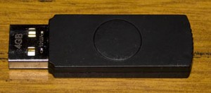
When inserting the thumbdrive it would recognise it however it would ask to insert a disk when clicking on the volume, so let’s open it up.
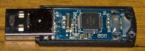
It was very easy to open up and upon first glance the build quality doesn’t seem too great but then again it’s a generic USB drive. We can see that it seems PCB wasn’t exactly made for the case which is why they have the glue to hold it in place.
(more…)
Read Full Post »
Posted in Projects on Mar 10th, 2012
I received a comment by Steve asking if I was going to combine the SATL and SAVL together. It sounded like a good idea to me so I’ve gone ahead and done just that.
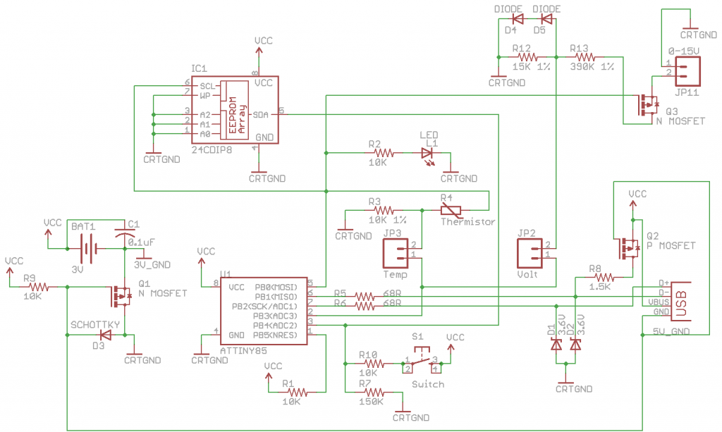
The schematic was updated with the voltage sensing circuit, I added in a Mosfet so that we only draw power from the voltage source when needed and you’ll notice there are 2 jumpers – Temp and Volt. You can switch between logging temperature and voltage by completing the connection of the jumper and modifying a variable with button presses.
(more…)
Read Full Post »
Posted in Projects on Mar 4th, 2012
As discussed last week the Standalone Temperature Logger has now been updated to v3.0.
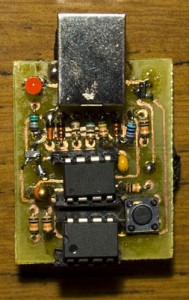
The PCB works well, with a few more parts needing top layer soldering it was a bit trickier.
The improvements made were:
- Added external I2C EEPROM support with automatic EEPROM size checking
- Updated 10K resistor divider to 1% tolerance
- Added 28 seconds to delay options available
- Updated temperature resolution to be 0.65C which is rounded up or down in 0.5 – 1C increments thanks to the suggestion made by tytower
Download SATL_v3.0 or view the updated Standalone Temperature Logger project page.
Increasing the resolution of data saved to EEPROM
A user named tytower left me a comment about increasing the resolution range that the SATL uses when saving to the EEPROM from my value 90 to 255 to use 1 to 255 which has prompted me to include his suggestions in the SATL v3.0. Tytower explained that the temperature range is -40C to 125 which is 165 data points and if we take the maximum value of data stored in the EEPROM 255 (minus 1 for the value 0 being our stop bit) and divide by 165, we get 1.545 which means we can increase our resolution by 1.5x. If we divide 165 by 255, our new resolution is 0.65C degrees (before I just had it as 1C) and to keep things nice I’ll round up or down to 0 or 0.5.
(more…)
Read Full Post »
Posted in Projects on Feb 25th, 2012
Last week we looked at SoftI2C so we could use an I2C EEPROM on any of our AVR’s pins and now it’s time to apply that to the Standalone Temperature Logger as the internal EEPROM of 512 bytes is a bit limiting.
Identifying the pins to apply I2C to
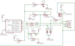
The first step is to identify which 2 pins we can use, we rule out the USB pins PB1 and PB2. After some testing I found PB0 for the clock and PB4 for the data seem to work well. In SoftI2C the clock is only ever an output, we have a line like that already, the LED one PB0. The data line changes between an input with pull-up resistor and output, we also have a 100k pull-down to ground which you’d think should affect the pull up but we’ll see why it shouldn’t.

The reason it shouldn’t is because the internal pull-up resistor is between 20K and 50K per the datasheet page 167. Since it’s a low value resistor compared to our 100k resistor it makes a desirable voltage divider.
(more…)
Read Full Post »


