Posted in Projects on Mar 12th, 2016
From our last part we looked at choosing capacitors for our LDO, testing our I2C timing, switching to a 1Mbit EEPROM and using EEPROM page writes. This time we’ll look at adding in the TMP102 sensor, experimenting with I2C pull-ups, re-testing the voltage switcher diode and other little improvements.
It has been a good while since I’ve worked on this project, though it’s not all bad, it does give me a chance to re-look at the project and pick up on things I might have missed.
Adding the TMP102
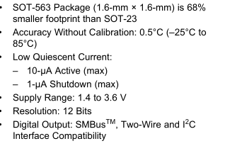
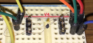
The TMP102 is a very small I2C temperature sensor with 0.5C accuracy (typical, -25C to 85C), 12 bit resolution, 1.4 to 3.6V supply and low current at 1uA shutdown and 10uA active plus it’s much smaller than what I thought so I had to use enamel wire to connect to it.
#define TMP102_TEMP_REG 0x00
#define TMP102_CONFIG_REG 0x01
#define TMP102_CONFIG_SD_MODE 0x01
#define TMP102_CONFIG_EM 0x10
#define TMP102_CONFIG_ONESHOT 0x80
...
if (!soft_i2c_master_start((deviceAddr<<1) | I2C_WRITE)) return false;
if (!soft_i2c_master_write(TMP102_CONFIG_REG)) return false;
if (!soft_i2c_master_write(TMP102_CONFIG_SD_MODE)) return false;
if (!soft_i2c_master_write(TMP102_CONFIG_EM)) return false;
soft_i2c_master_stop();
By default the TMP102 operates in a continuous conversion mode where it samples the temperature and puts it in a register at power on, we should disable this feature by enabling shutdown mode (SD).
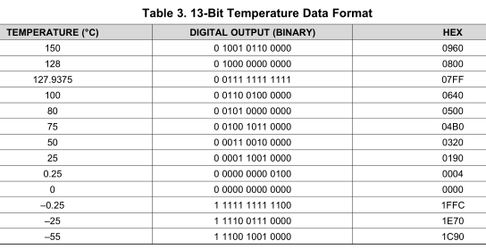
We change from 12bit data mode which lets us measure -55 to 128C to 13bit mode which does -55 to 150C by setting the extended mode bit and write the above changes by referencing the configuration register (0x01) first.
(more…)
Read Full Post »
Posted in Teardowns on Feb 15th, 2016
Today we’ll be taking a look at the D-Link 16-Port 10/100Mbps Desktop Switch (DES-1016D), it’s just a simple 16 port 10/100 switch and I don’t expect there to be too much going on inside just like we’ve seen with other switches.
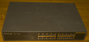
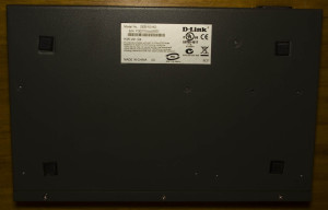
Three screws later and we’re in.
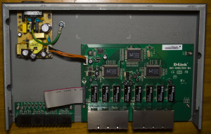
We have 3 separate boards, the power supply board taking the AC in which connects to the main board and then another small board for the LEDs. PCB date code is 16th week of 2007.
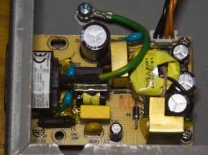
The power supply board looks decent with a clean design.
(more…)
Read Full Post »
Posted in Arduino, Tinkering on Jan 6th, 2016
Lately my blog has been focused on quadcopters / RC cars and here’s another little one, I’ve been wanting to try out Acro mode but would rather not crash a whole lot to test it out. There’s a program called FPV Freerider which lets you simulate the quadcopter on a few different maps. Normally you would use a Flight Simulator Cable however I didn’t want to wait and they were out of stock locally.
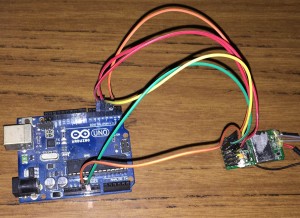
I happened to stumble upon Giuseppe’s Urso’s Blog which had some code for this exact purpose but for some reason only my first channel was working with my Turnigy iA6 receiver. The format being sent by 9600 baud serial was the FMS PIC 9600 which involves a special byte mixed in with the number of channels, another byte for buttons and then each channel has it’s own byte ranging from 0 to 255. Now that we have the format, I can write some code.
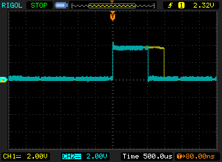
I found that my iA6 receiver outputs all it’s channels at the same time, i.e all at the same time and not one after another like some other receivers might, it actually makes it easier for us as all we need is an interrupt on any of the pins and then we start counting. Connect RX channel 1 to Arduino pin 2, RX channel 2 to Arduino pin 3 and so on.
#define RX_CHANNELS 4

volatile uint16_t ch1Result = 127;
...

void setup() {
  Serial.begin(9600);

  // Set inputs
  for (uint8_t x = 2; x < RX_CHANNELS + 2; x++) {
    pinMode(x,INPUT);
  }

  // Attach interrupt to pin 2 as rising
  attachInterrupt(0, time_channels, RISING);

  // Reuse Timer1 to count the microseconds after pin 2, etc go high
  TCCR1A = 0;
  TIMSK1 = 0;
  TIFR1 = 0;
  TCNT1 = 0;
  TCCR1B = (1<<CS10);
}
After playing around with the Arduino micros function, it had glitching every few results so I used the timers directly. We setup the pins as inputs, attach the interrupt INT0 to pin 2 to only trigger when the pin goes high and reset the timer to the default.
(more…)
Read Full Post »
Posted in Teardowns on Dec 18th, 2015
Today we’ve got another old device to look into, the D-Link DSL-502T ADSL2 Modem which is simple ADSL2 modem that has 10/100 Ethernet and USB.

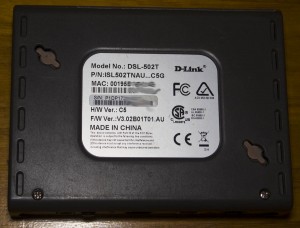

Two screws later and we’re in.
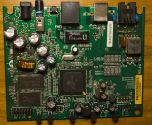
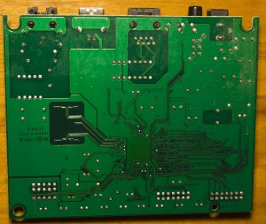
As with these old devices there’s lots of capacitors on board, we have 4x Everon 1000uF and 2x Taicon 220uF near the input and we have an AP34063 DC-DC with a reasonably sized inductor and it looks like the input DC jack was intended for an AC adapter so they just bypassed the diodes with links. PCB date code is 7th week of 2003.
(more…)
Read Full Post »
Posted in Tinkering on Nov 25th, 2015
Update 23 May 2017: There is an easier way to get Error rate in Betaflight, update your i6 transmitter with the 10Ch mod and specify Error as a channel , no soldering required – https://github.com/benb0jangles/FlySky-i6-Mod-/issues/17#issuecomment-278679083 (be aware, it will wipe your model memory)
Previously I was able to modify the Turnigy TGY-i6 transmitter to read the signal strength (RSSI) byte and illuminate an LED near the FPV display if the error rate was high so you could easily tell that it’s probably a good idea to turn around. There was a comment from Paul asking if there was a way to read the RSSI from the receiver itself and then pass this onto the flight controller or OSD. (This isn’t really RSSI but just error rate which is a good indicator when you are going to lose signal as you are too far away)
https://www.youtube.com/watch?v=uHnYfxDknrY
This sounded like a good idea so I went ahead and did just that with a spare iA6 receiver (I suspect the iA6B should be the same. Edit – it’s different, see end of post). Firstly lets do a quick teardown of the receiver.
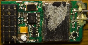
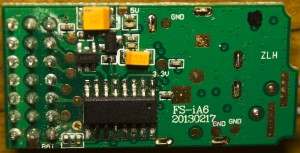
On the top we’ve got our 2 antennas going to the RF can with a microcontroller (TG84023) which would be converting the incoming data to the 6 channels, an 8MHz crystal/oscillator and on the bottom we have another MCU (no label). The PCB marking reads FS-iA6 (Flysky branded), 20130217 and it’s got 3.3V and 5V which I’ve verified so the little 3 or 6 pin packages would be an LDO for 3.3V and DC-DC boost/buck for the 5V and I think the inductor is under the white potting compound.
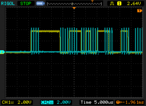
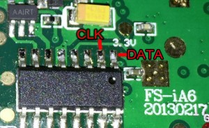
After a bit of probing around, the MCU on the bottom looked to be producing a clock output of 1MHz and some serial data. One initial problem that I thought might be an issue is with syncing the serial data to the clock pulses as at the start and near the middle there is a 4 clock block but it turns out there is an even number of them so it works out just fine.
(more…)
Read Full Post »
Posted in Projects on Nov 17th, 2015
The current doorbell we’re using at home is a bit old now and it can play up from time to time (it’s one where you rotate some screws to give a certain combination to link up with the transmitter). A majority of my time for the last few months have been with RC and now I’ve got some spare parts we can put to good use.
https://www.youtube.com/watch?v=r7_RbnRNwxY
My idea is to use a nRF24L01+ with an ATtiny for the transmitter and receiver, an old small video camera bought off Ebay, a 10mW 5.8GHz video transmitter, 5.8GHz receiver, 4.3″ monitor and some batteries. I have some more ideas for the next iteration of this project found at the end.
Doorbell Transmitter
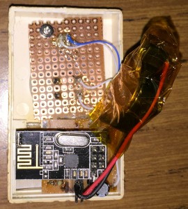
So the first part is the transmitter, I could make an acrylic box with the CNC but it wouldn’t look quite as good as a proper enclosure (though I could stack the layers), a 3D printer would be perfect for this job but since I don’t have one I decided to re-use the enclosure. I took out all the electronics and lined up a button and LED on a veroboard and it fit in nicely.
(more…)
Read Full Post »
Posted in Teardowns on Oct 25th, 2015
Today we’ll be taking a look at a modern device the Synology DS112J Single Bay NAS (Network Attached Storage) which contains a single hard drive with Gigabit Ethernet and 2x USB 2.0 ports. Most of the magic with this device is from the software called the DSM which is a easy to use interface and lets you install additional apps to it, like a download manager, camera surveillance, etc plus third party apps too.
Two screws later and we’re in.
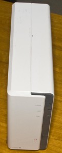
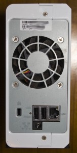
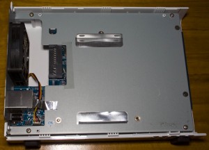
Just from the initial view, they spent the time to tape down the fan wire, be it for EMI or tidiness so we can assume there’s a good chance that the quality inside should be pretty good.
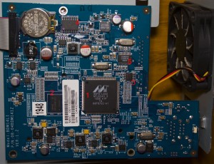
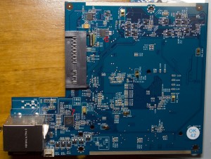
We’ve got quite a few DC-DC converters (FR9888, ZT1525) and what look to be some N/P mosfets too (AP4410GM / AP4953GM), one’s near the input jack near a diode possibly for some input protection and 2x P mosfets near a PWM driver chip (uP1504T). They’ve got a cable going to the front panel board tapped down too which just has some LEDs and a button and there’s also a SMD buzzer (AD-7504) which at first glance didn’t look like a buzzer. On the bottom board they have the RTC crystal glued down and have 7 little EMI pads touching the metal case.
(more…)
Read Full Post »
Posted in Teardowns on Sep 27th, 2015
Today we’ll be taking a look at another old device the Netgear ProSafe 802.11g Wireless VPN Firewall (FVG318), it’s a Wireless b/g access point with 1x 10/100 Mbps WAN and 8 ports 10/100 Mbps LAN switch with SPI firewall, the ability to block addresses, services, protocols, keywords, with 8 IPSec VPN tunnels, etc.

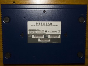

One screw later and we’re in.
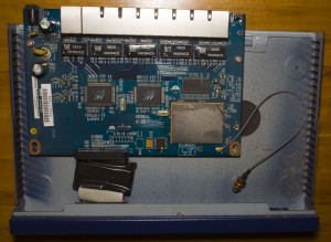

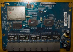
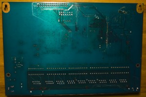
We’ve got our board with only a few major components so it’s a bit more modern than the last Netgear device we took apart. There’s a ribbon cable with a choke for the front panel lights and an external antenna, there’s the possibility of adding another antenna too. There is a MPS MP1410 SMPS with 3 smaller regulators.
(more…)
Read Full Post »
Posted in Tinkering on Sep 3rd, 2015
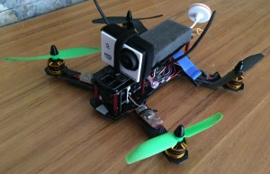
I’ve mentioned before that I’ve been looking into quadcopters and built my ZMR250 quadcopter a few months ago which is working well, a few modifications have been made here and there; and some are still to come.
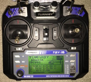
One problem with the transmitter is that there isn’t a way that I’ve found to make it beep or light up if you exceed a certain communication error rate, the further you go or the more objects in your line of sight, the higher the error rate becomes. You can glance down at the remote and check it there but when you are focused on your FPV monitor you can easily forgot so I would like a better way. There may be a way to do it in software but I decided to try the hardware route.
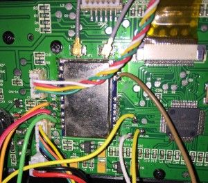
To start, I thought I’d go digging around the transmitter to see if I could find an RSSI pin by measuring voltages when I had the receiver on the quadcopter in an open space and then compare to in a microwave (as it blocks most of the 2.4GHz radio). I couldn’t find an RSSI pin so it was time to break out the logic analyser and capture data from the radio module, there had to be some communication between the MCU and radio module in order for it to display on the LCD.
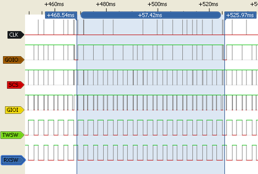
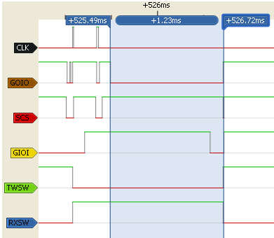
Once thing that was very noticeable was the GOIO pin would pulse low for about 1.2ms every 57ms when it was in range. When the error rate got higher, it would drop to 150ms and sometimes 300ms but after more testing it seemed unreliable.
(more…)
Read Full Post »
Posted in Teardowns on Aug 22nd, 2015
Just a quick one today, we’re looking at a generic DisplayPort to VGA Adapter that was reported faulty by an end user, I believe it was lines on the screen/flicking or similar.
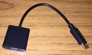
We easily pop out the covers on each end.
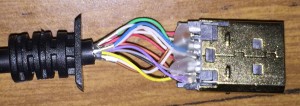
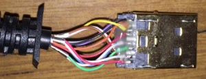
The DisplayPort connector is directly wired and glued, not too bad.
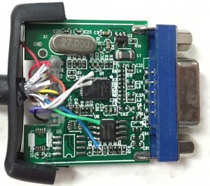
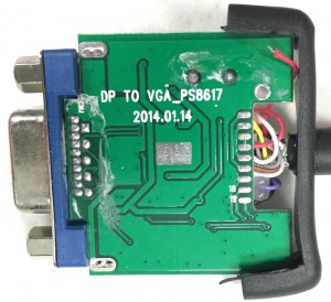
For the VGA side, we have the PCB with 2 chips but also have 5 wires just dangling around, that can’t be good. PCB Date is 14th January 2014.
(more…)
Read Full Post »


